
Method and apparatus for the self-diagnosis of an exhaust gas probe

a technology of exhaust gas probe and self-diagnosis, which is applied in the direction of mechanical equipment, engine components, machines/engines, etc., can solve the problems of faulty signal interpretation and defective particle sensor, and achieve the effect of improving the self-diagnosis of the exhaust gas prob

Active Publication Date: 2011-10-20
ROBERT BOSCH GMBH
View PDF3 Cites 12 Cited by
  • Summary
  • Abstract
  • Description
  • Claims
  • Application Information

AI Technical Summary

Benefits of technology

[0010]It is therefore an object of the invention to provide a method which leads to improved self-diagnosis of an exhaust gas probe, in particular of a particle sensor.
[0015]As a result of self-diagnosis of this type, it is possible, for example, to detect defective particle sensors, the electrodes of which have been damaged during the production or in use over the service life of the sensor, and to inform the driver / operator of the vehicle / system by way of visual and / or acoustic warnings if the sensor has failed totally. One preferred use of the method and of its variants, as will be described in the following text, provides the regeneration of the particle sensor in the context of on board diagnosis in a diesel internal combustion engine. In this application, what is important is, in particular, precise and reproducible diagnosis of the particle loading of a soot particle filter (diesel particulate filter, DPF) which is arranged in the exhaust gas section of the diesel internal combustion engine. This is advantageous, in particular, in particle sensors which, as viewed in the flow direction of the exhaust gas, are installed downstream of a particle filter, and it is unclear here whether the particle sensor functions correctly and the exhaust gas only has a low soot proportion to none at all or whether the particle sensor is faulty and the exhaust gas is possibly heavily loaded with soot, however. Furthermore, blockages in the protective tube or even deliberate removal of the particle filter can be diagnosed. Faulty measurements can likewise be detected as such and either a corresponding correction of the measured data can be performed or, for example, an exchange of the sensor can be initiated. Considerably improved operational reliability in comparison with the prior art can therefore be achieved.
[0025]It is advantageous with regard to a simple evaluation if the diagnosis is carried out during a phase at a constantly controlled temperature or during the regeneration of the exhaust gas probe which is configured as a particle sensor during a heating ramp for achieving a free burning temperature required for soot elimination or in the case of deviations of the measured actual temperature from the expected temperature setpoint value.

Problems solved by technology

However, the fact that no signal is supplied by a sensor can also mean that the particle sensor is defective and therefore a possibly likewise defective particle filter is not detected as being defective.
In addition, sooting of the protective tube can also lead to a faulty interpretation of the signals.

Method used


Image

  • Method and apparatus for the self-diagnosis of an exhaust gas probe
  • Method and apparatus for the self-diagnosis of an exhaust gas probe

Examples


Embodiment Construction

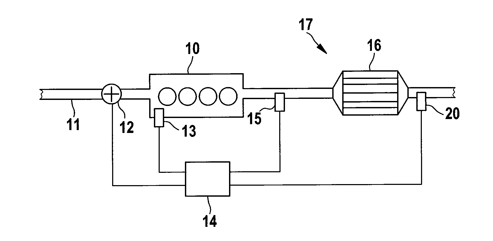
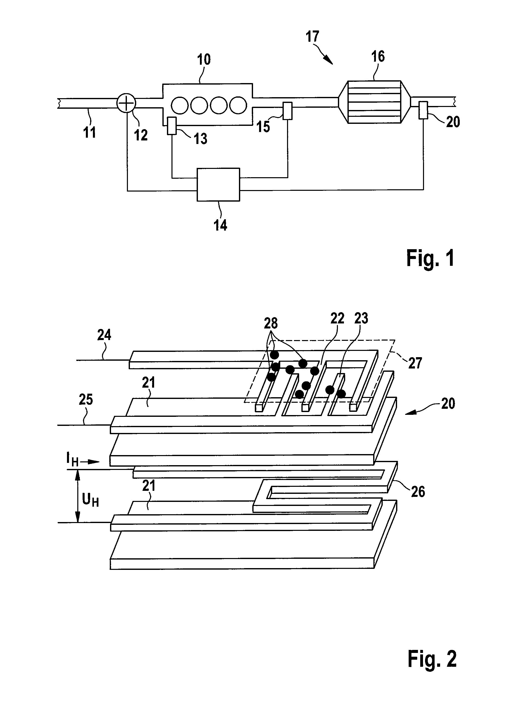
[0030]FIG. 1 diagrammatically shows the technical surroundings, in which the method according to the invention can be applied. An internal combustion engine 10 which can be configured as a diesel engine is fed combustion air via an air feed means 11. Here, the air quantity of the combustion air can be determined by means of an air mass flow rate meter 12 in the air feed means 11. The air quantity can be used in a correction of an accretion probability of particles present in the exhaust gas of the internal combustion engine 10. The exhaust gas of the internal combustion engine 10 is discharged via an exhaust gas section 17, in which an exhaust gas purification system 16 is arranged. Said exhaust gas purification system 16 can be configured as a diesel particle filter. Furthermore, an exhaust gas probe 15 which is configured as a lambda probe and an exhaust gas probe 20 which is configured as a particle sensor are arranged in the exhaust gas section 17, the signals of which exhaust g...


PUM


Abstract

A method for the self-diagnosis of an exhaust gas probe (20). The exhaust gas probe (20) has at least one heating element (26). The method includes a modeled heat output PH is determined for the heating element (26) by means of a computer program comparing parameters of the gas stream with a measured heat output, and determining, when the parameters of the gas stream exceeds the measured heat output by more than a defined tolerance limit, that one of the exhaust gas probe (20) is defective, and an exhaust gas section (17) in which the exhaust gas probe (20) is installed is faulty.

Description

BACKGROUND OF THE INVENTION[0001]The invention relates to a method for the self-diagnosis of an exhaust gas probe, the exhaust gas probe having at least one heating element.[0002]Furthermore, the invention relates to an apparatus for the self-diagnosis of a corresponding exhaust gas probe, the exhaust gas probe being connected to an engine controller or a sensor control unit, and the engine controller or the sensor control unit having devices for the diagnosis of the exhaust gas probe.[0003]Particle sensors are used nowadays, for example, for monitoring the soot emission of internal combustion engines and for on board diagnosis (OBD), for example functionally monitoring particle filters. Here, collecting, resistive particle sensors (particle mass sensors or PM sensors) are known which evaluate a change in the electric properties of an interdigital electrode structure on account of particle accretions. Two or more electrodes can be provided which preferably engage into one another in...

Claims


Application Information

Patent Timeline
Patent Type & Authority Applications(United States)
IPC IPC(8): F01N11/00
CPCF01N11/00Y02T10/47F01N2560/20F01N2560/00Y02T10/40
Inventor BAUMANN, THOMASBAARS, ENNOGRABIS, JOHANNESHAGEMANN, BENJAMINKAMP, BERNHARD
Owner ROBERT BOSCH GMBH
Learn More