HF Ignition Device

a high-frequency ignition and ignition device technology, applied in engine ignition, other installations, electrical devices, etc., can solve the problems of premature failure difficult operation, and considerable wear of hf ignition devices, and achieve the effect of improving dielectric strength

Active Publication Date: 2011-10-20
BORGWARNER BERU SYST
View PDF18 Cites 22 Cited by
  • Summary
  • Abstract
  • Description
  • Claims
  • Application Information

AI Technical Summary

Benefits of technology

[0006]Surprisingly, the dielectric strength can be markedly improved by placing an electrically conductive filling material in the channel of the insulating body, which wets the channel along the entire length that is enclosed by the outer conductor. The inner surface of the insulating body is therefore wetted by the filling material at least on the longitudinal section of the insulating body enclosed by the outer conductor. The channel can also be wetted with filling material in sections of the insulating body that extend out of the outer conductor, but this is not necessary.

Problems solved by technology

HF ignition devices are an alternative to conventional spark plugs which induce ignition using an arc discharge and are subject to considerable wear due to electrode erosion.
The reason is that, at frequencies of typically at least one MHz and voltages of a few kV, e.g. 50 kV to 500 kV, the dielectric strength during operation has proven to be problematic.
Voltage overloads and partial discharges often cause an HF ignition device to fail prematurely.

Method used


Image

  • HF Ignition Device
  • HF Ignition Device
  • HF Ignition Device

Examples


Embodiment Construction

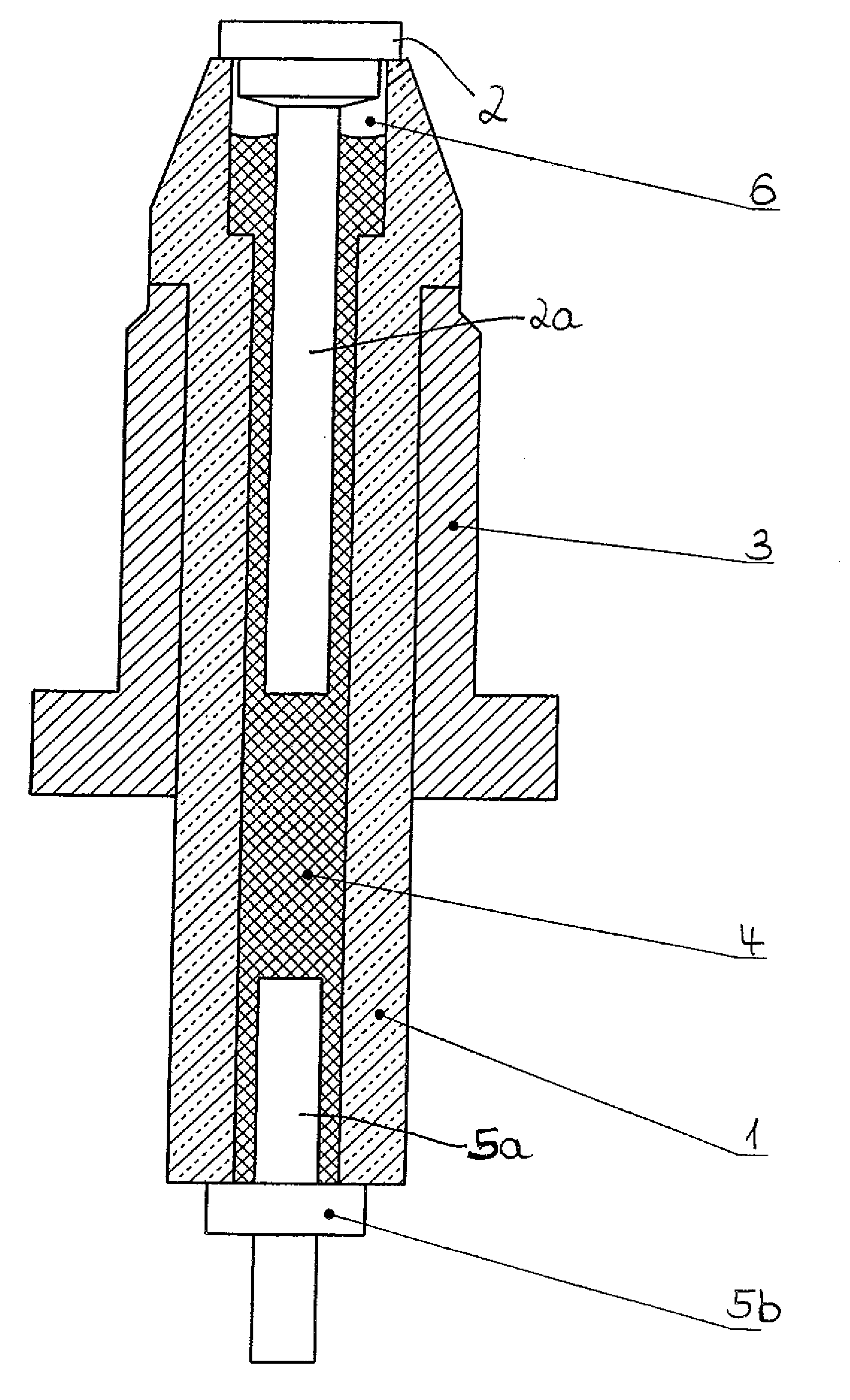
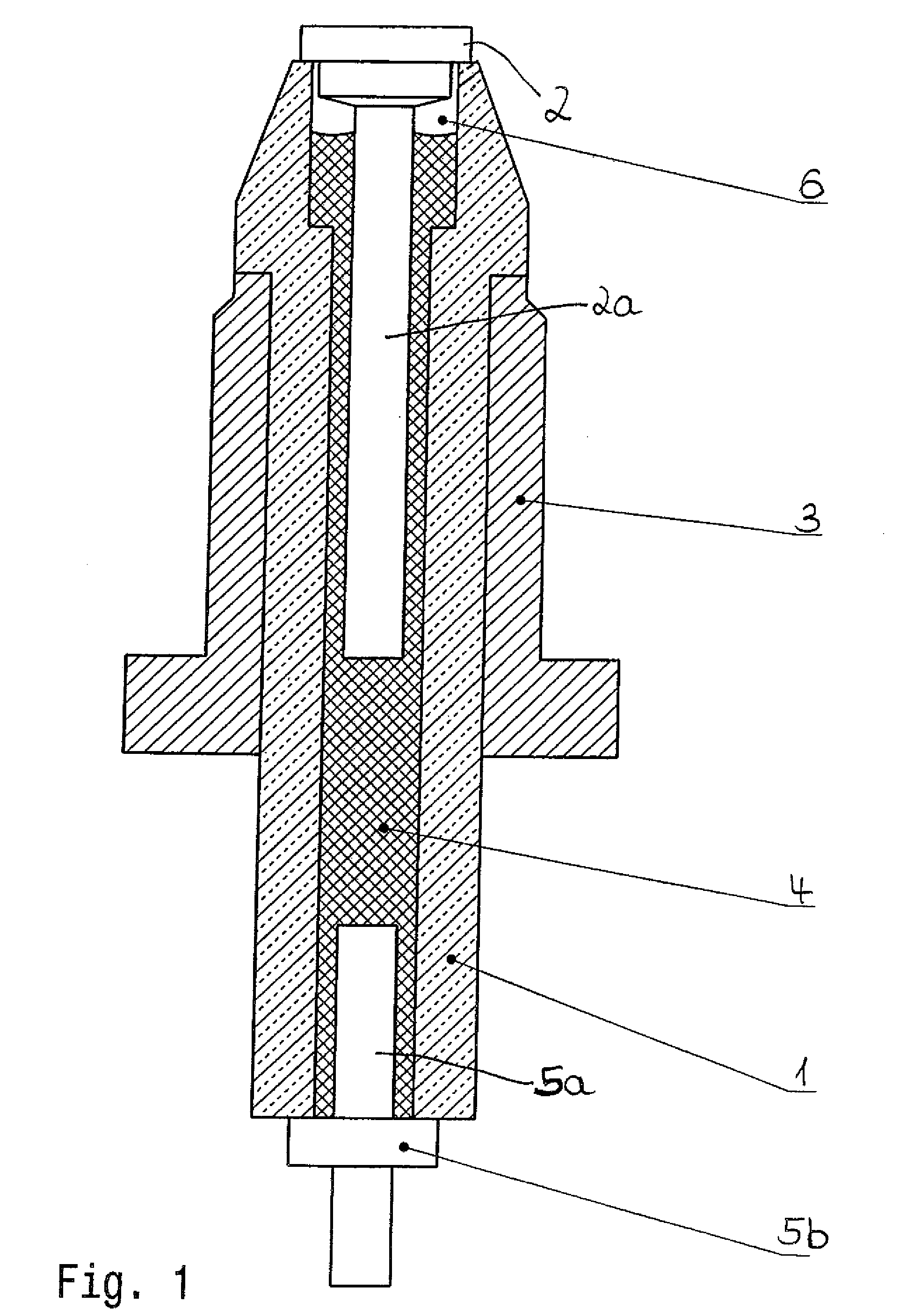
[0026]The HF ignition device depicted schematically in FIG. 1 comprises an insulating body 1 which has an ignition electrode 2 on one end and is enclosed by an outer conductor 3 along a portion of the length thereof. A channel, preferably a bore, extends in insulating body 1 and contains an inner conductor which, in the embodiment shown, is formed by an electrically conductive filling material 4 and conductor pieces 2a, 5a inserted into the two ends of the channel.

[0027]Outer conductor 3, in combination with the inner conductor, forms a capacitor, the dielectric of which is insulating body 1. This capacitor is part of a circuit which is not depicted and is used to generate high-frequency alternating voltage. Further elements of said circuit can be disposed in a housing which is not depicted and extends out of the HF ignition device shown in FIG. 1.

[0028]To produce the HF ignition device shown, the channel is closed at one end using an electrically conductive, preferably metallic clo...


PUM


Abstract

The invention relates to an HF ignition device for igniting a fuel in an internal combustion engine with a corona discharge, comprising an ignition electrode, an insulating body on which the ignition electrode is mounted, the insulating body having a continuous channel in which an inner conductor leading to the ignition electrode is disposed, and an outer conductor which encloses the insulating body and, in combination with a section of the inner conductor, forms a capacitor, wherein the channel is filled with an electrically conductive filling material which encloses at least one conductor piece that forms at least one section of the inner conductor.

Description

[0001]The invention relates to a high-frequency ignition device for igniting fuel with a corona discharge. A HF ignition device of this type is known from EP 1 515 594 A2.[0002]To ignite a combustible gas mixture in an engine, the ignition electrode of such an HF ignition device is excited using a suitable circuit, e.g. an HF oscillating circuit. A high-frequency high voltage is produced as a result, creating a plasma in the combustion chamber of the engine and thereby inducing ignition. Details of igniting combustible gas mixtures in a engine by means of a corona discharge are described in WO 2010 / 011838 A1 and WO 2004 / 063560 A1 which are incorporated into the present application by reference.[0003]One part of the circuit used to generate the high-frequency alternating voltage is a capacitor, the dielectric of which is formed by the insulator body which encloses the inner conductor leading to the ignition electrode.[0004]HF ignition devices are an alternative to conventional spark ...

Claims


Application Information

Patent Timeline
Patent Type & Authority Applications(United States)
IPC IPC(8): F02P23/00
CPCH01T13/50
Inventor BRAEUCHLE, GERDHEILMANN, FELIZITASACHTSTAETTER, TOMGIFFELS, THOMASMAYER, CHRISTIAN
Owner BORGWARNER BERU SYST
Why Eureka
Try Eureka