Vacuum Pumped Liquid Cooling System for Computers

a liquid cooling system and vacuum pump technology, applied in indirect heat exchangers, lighting and heating apparatus, instruments, etc., can solve the problem of limiting the delta pressure available to each heat exchanger, and achieve the effect of reducing the volume of water, increasing the water flow and turbulence, and reducing the amount of water

Inactive Publication Date: 2011-10-20
CHILLDYNE
View PDF14 Cites 31 Cited by
  • Summary
  • Abstract
  • Description
  • Claims
  • Application Information

AI Technical Summary

Benefits of technology

[0008]Each server may have an inlet pressure regulator and an outlet pressure regulator in order to maintain a desired delta pressure across the CPU heat exchanger. Each CPU will typically have a temperature sensor, and an increase in temperature over the inlet water temperature may indicate a problem with the heat exchanger. This may be used to indicate a need for repair. A temperature sensor, such as a thermistor, may be used to measure the inlet water temperature. Flowmeters, such as a rotameter or turbine meter with a digital readout, may also be used to monitor the flow. A filter may be used after the cooling tower and before the heat exchanger to prevent clogging of the heat exchanger passages. Chemical additives may be used to prevent fouling of the heat exchanger with biological films and to prevent corrosion. The internal heat exchanger passages may be plated or anodized to prevent corrosion.Local Air Release
[0010]Each server or server rack may be connected with a dry disconnect system that allows for the automatic draining of the server system. This connector may include the supply and return flows. Such flows may be coaxial, in order to allow for a small interconnect. The system is preferably designed to remove all of the water from inside each subsystem such as a CPU, server or server rack during the disconnection process. For example, if the server contains 1 cc of water, and the flow rate is 150 cc / minute of water, then it will take less than 1 second to drain the water out of the system. As the water is replaced by air, the flow resistance of the heat exchanger decreases, so the process may happen in less than 0.5 seconds. This draining process is helped by the following connector arrangement. To detach the connector in one embodiment discussed below, the operator would depress a button that operates a three-way valve that cuts off inlet water flow and vents to allow air into the system. Negative pressure on the return side of the connector holds the connector in until air reaches the outlet. At this point, the negative pressure in the system is diminished due to the much lower delta pressure of air flowing through the heat exchanger and then the connector may be easily removed. Removal of the connector seals the outlet so that air does not continue to flow into the cooling system return flow path. The button stays depressed, thereby sealing off the inlet. To attach the connector, the operator would insert the coupling, which would connect the return path, and the button would automatically release, which would allow the supply flow to reach the components. This system may also be actuated with a twist instead of a button push. The connector may utilize a sacrificial metal, such as zinc or utilize electrical potential to prevent corrosion inside the CPU heat exchanger.
[0016]The heat exchanger may use a helical flow pattern to put a long path into a short passage. This may be accomplished by placing a threaded rod in a metal tube so that the flow must take a long path through the heat exchanger at a high velocity. This has the added benefit of reducing the volume of water in the heat exchanger, thereby reducing the amount of water that needs to be cleared to service the heat exchanger. Alternatively, a rod with a tortuous path in relief may be used to increase the water flow and turbulence. The rod and cylinder may be square or of any other cylindrical shape. The turbulator may be designed so that some of the water flows over the flow passages in an axial direction. This axial flow will interact with the helical flow to provide swirl in the heat transfer passages in order to increase heat transfer. In addition, the axial flow will reduce the flow resistance of the heat exchanger. This arrangement may be particularly useful in situations where the flow is laminar. For high power dissipation systems, multiple parallel turbulators may be used. In some installations, a flat plate heat exchanger may be used.

Problems solved by technology

This limits the available delta pressure available to each heat exchanger to the difference between the vapor pressure of the warmest water within the system and the local absolute pressures.

Method used


Image

  • Vacuum Pumped Liquid Cooling System for Computers
  • Vacuum Pumped Liquid Cooling System for Computers
  • Vacuum Pumped Liquid Cooling System for Computers

Examples


Embodiment Construction

[0028]The following detailed description presents a description of certain example embodiments of the present invention. In this description, reference is made to the drawings wherein like parts are designated with like numerals throughout.

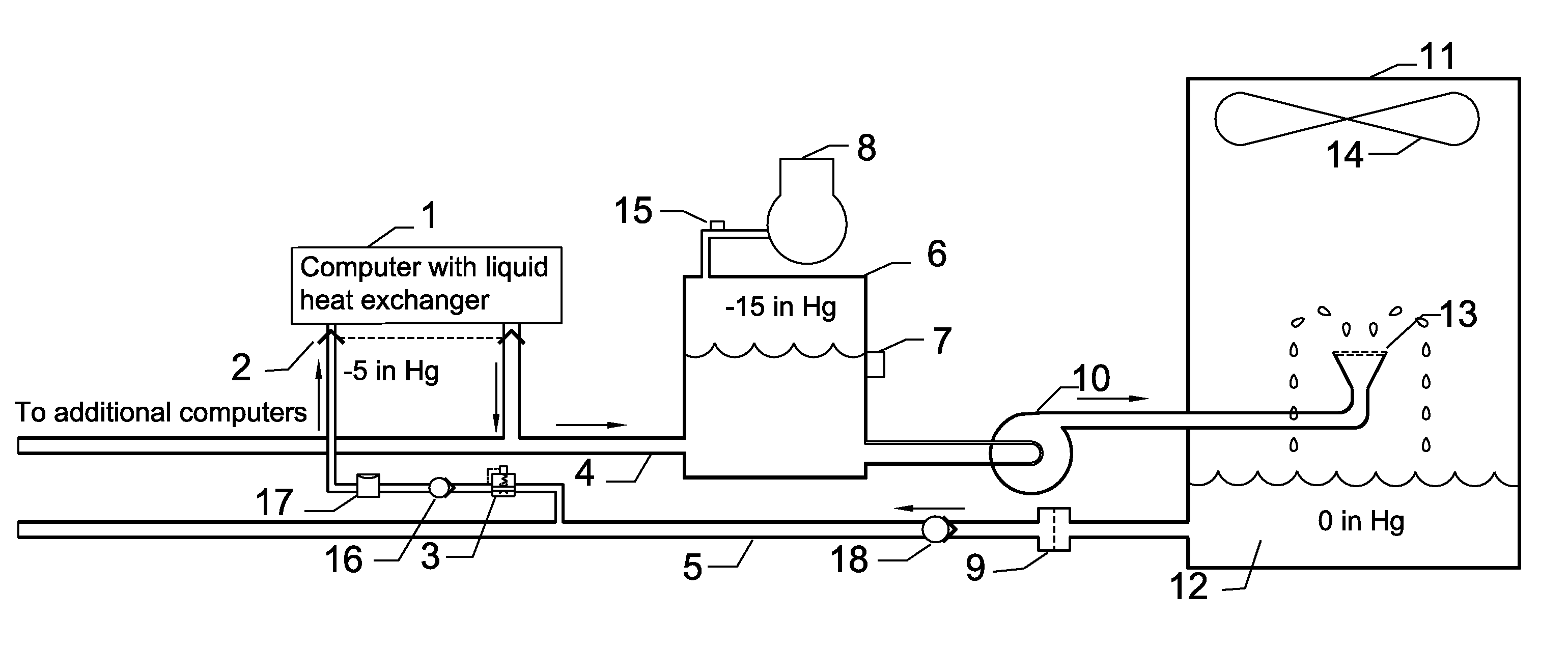
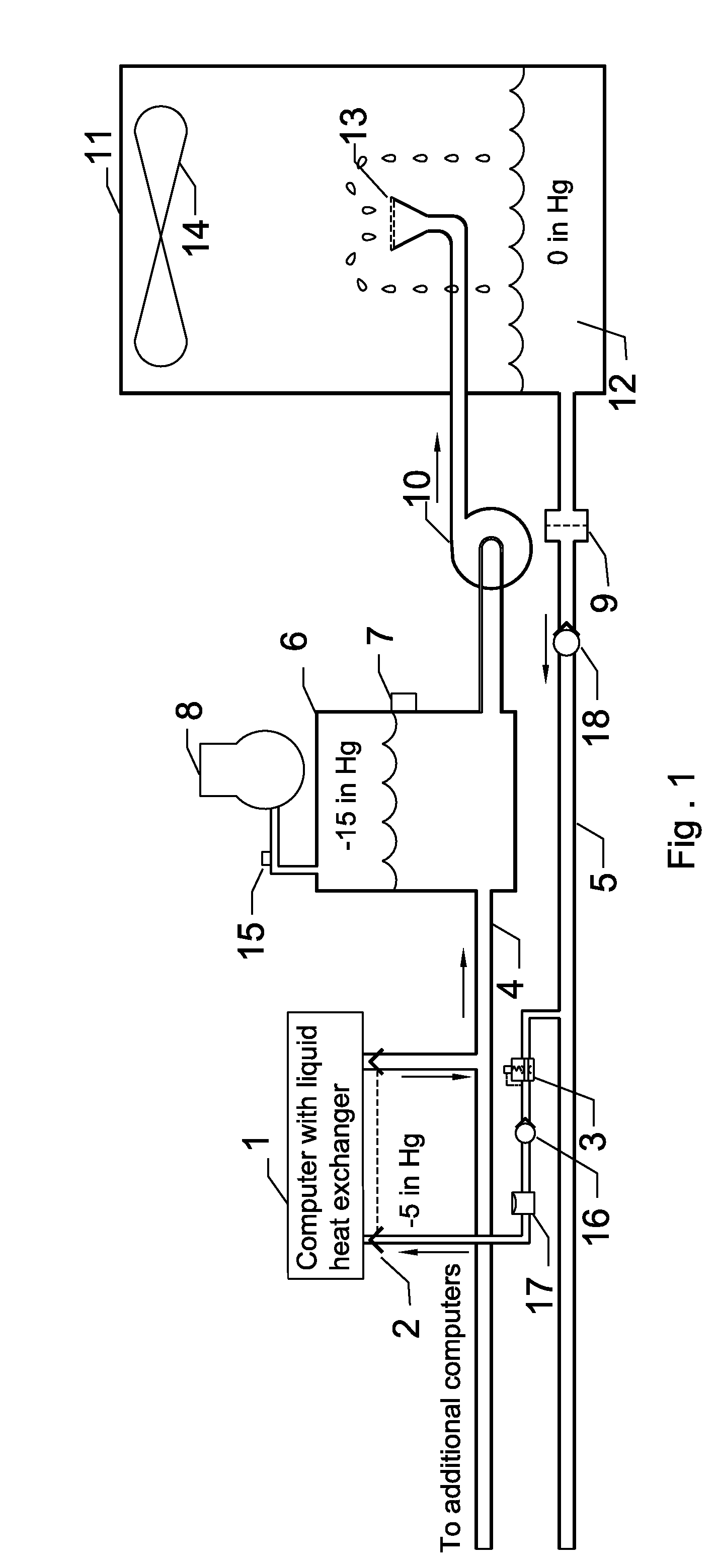
[0029]Referring to the example embodiment shown in FIG. 1, a supply of liquid coolant such as water 12 is maintained at a low temperature by the evaporation of the water as it flows out of nozzle 13. The humid air flows out due to fan 14 in cooling tower 11. Due to the low pressure in the reservoir 6, the water flows through a filter 9, and check valve 18 and a supply pipe 5, through a pressure regulator 3, through another check valve with a cracking pressure of approximately 1 inch HG, through and vacuum accumulator 17 and then through a fluid connector 2, to the computer with internal heat exchanger 1. The water then receives heat from the internal electronic components in the computer and flows out through the connector to an extraction pipe 4 ...


PUM


Abstract

A reliable, leak tolerant liquid cooling system with a backup air-cooling system for computers is provided. The system may use a vacuum pump and a liquid pump in combination to provide negative fluid pressure so that liquid does not leak out of the system near electrical components. The system distributes flow and pressure with a series of pressure regulating valves so that an array of computers can be serviced by a single cooling system. The system provides both air and liquid cooling so that if the liquid cooling system does not provide adequate cooling, the air cooling system will be automatically activated. A connector system is provided to automatically evacuate the liquid from the heat exchangers before they are disconnected.

Description

BACKGROUND OF THE DISCLOSUREBrief Description of the Related Art[0001]Arrays of electronic computers, such as are found in data centers, generate a great deal of heat. A typical CPU puts out over 100 watts and has a maximum case temperature of about 60 C. A typical rack of 88 CPUs may put out 9 Kw. The maximum outside temperature at a hot urban location might be 45 C, so the heat flow goes with the gradient. Theoretically, no refrigeration should be required, yet the standard way to keep data centers cool is to use vapor compression refrigeration systems at least part of the time. These systems often use more power that the computers themselves. These systems use air as the heat transfer medium, and it is due to the low heat capacity and thermal conductivity of air that refrigeration must be used to overcome the thermal resistance of multiple air heat exchangers. Some operators use evaporation of water to cool water-to-air heat exchangers which then in turn cool computers, and this ...

Claims


Application Information

Patent Timeline
Patent Type & Authority Applications(United States)
IPC IPC(8): F28D15/00
CPCF28D7/028F28D2021/0019F28F1/16F28F7/02H05K7/20836H05K7/20272H05K7/2079F28F2215/00G06F1/20
Inventor HARRINGTON, STEVE
Owner CHILLDYNE
Why Eureka
Try Eureka