Polymer Composition

a technology of polymer composition and polymer matrix, which is applied in the direction of organic conductors, metal/alloy conductors, conductive materials, etc., can solve the problems of internal stresses within the material, mechanical failure of the composite in the polymer matrix, and significant noise associated with the composi

Inactive Publication Date: 2011-10-20
PERATECH HOLDCO
View PDF4 Cites 17 Cited by
  • Summary
  • Abstract
  • Description
  • Claims
  • Application Information

AI Technical Summary

Benefits of technology

[0039]Whilst the dictionary definition of acicular is needle shaped, in the context of this patent application acicular shall be deemed to mean any particle having an aspect ratio greater than 1, i.e. a particle which is longer than it is wide. Such an acicular shaped particle need not necessarily ...

Problems solved by technology

This has been shown conclusively by the fact that mechanical failure of the composite occurs in the polymer matrix and not at the particle polymer interface.
Whilst the materials described in WO 98/33193 exhibit extreme changes in resistance when subject to force, it has been found that a significant amount of noise is associated with an electrical signal passing through the material.
However, this requires the use of binders that display relatively high shrinkage upon cure, resulting in internal stresses within the material, thereb...

Method used


Image

  • Polymer Composition
  • Polymer Composition
  • Polymer Composition

Examples


experiment i

[0074]In order to perform experiments three samples of quantum tunnelling composite were manufactured as shown in the table below using elastomeric silicone rubber polymer typical of the polymer type used in quantum tunnelling material described in WO 98 / 33193:

TABLE 1SampleSilicone / gNi 123 / gFT2000 / g110500210502310504

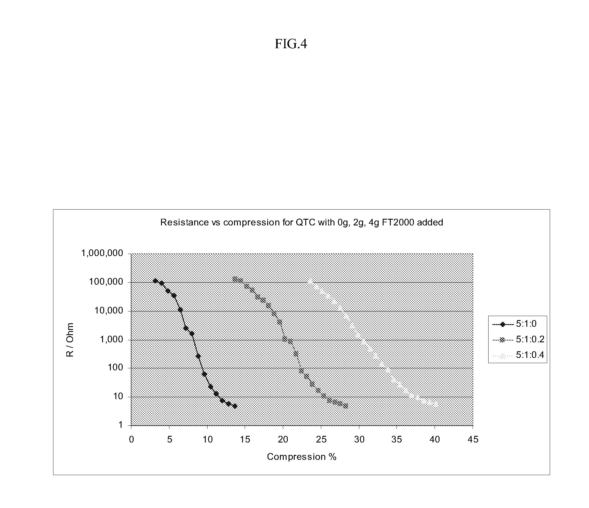
[0075]FIGS. 4 to 6 relate to experiments conducted on the materials of samples 1 to 3, i.e. loadings of FT-2000 of 0, 2 and 4 grams respectively.

[0076]The graph illustrated in FIG. 4 shows that adding FT-2000 reduces the sensitivity of samples to compression. Also, rate of change of resistance with compression is reduced with increasing amount of FT-2000 as indicated by the reducing steepness of slope as the proportion of FT-2000 is increased. Both these phenomena allow a quantum tunnelling composite to be tuned to a particular force region of interest.

[0077]The effects illustrated in FIG. 4 may be explained in mechanical and / or electrical terms. Adding FT-2000 to the ma...

experiment ii

[0086]Quantum tunnelling composites were manufactured using a solvent-based polymer binder, in the present example Polyplast PY383, with various loadings of Ni123 and FT-2000 in powder form. The total amount of powder mixed with the polymer was held constant, with the relative volume amounts of Ni123 and FT-2000 being varied, as shown in Table 2.

TABLE 2Ni123 %1009080706050403020100FT2000 %01020304050607080900

[0087]The volume ratio of uncured polymer binder to filler was 1:0.13 for all samples.

[0088]Referring now to FIGS. 7 and 8, these graphs relate to resistance of the sample being measured transverse to the direction of application of force. FIG. 7 shows that by manipulating the relative amounts of Ni123 and FT-2000 the start and end resistances can be changed. For samples having a Ni123 content of up to 90% the rate of change of resistance upon application of increasing force is substantially similar irrespective of the relative proportions of Ni123 and FT-2000. However, within t...


PUM


Abstract

A polymer composition comprises at least one substantially non-conductive polymer binder and at least first and second electrically conductive fillers. The first electrically conductive filler is comprised of particles having avoid-bearing structure; and the second electrically conductive filler is comprised of particles which are acicular in shape.

Description

FIELD OF THE INVENTION[0001]The present invention relates to a polymer composition and in particular to an elastomeric conductive polymer composition which displays controllable resistance / force characteristics and / or reduced noise level.BACKGROUND OF THE INVENTION[0002]Elastomeric conductive polymer compositions which exhibit changing electrical resistance when subjected to compressive or tensile forces are known. Such compositions are described in International patent application published under number WO 98 / 33193 and WO 99 / 38173.[0003]In WO 98 / 33193 an elastomeric conductive polymer composition comprises an electrically conductive filler encapsulated in an elastomeric polymer. The material is elastically deformable from a quiescent state in which the material behaves as an electrical insulator to a conductor when subjected to compressive or tensile forces.[0004]In WO 99 / 38173 a polymer composition is described which comprises a substantially non-conductive polymer and an electric...

Claims


Application Information

Patent Timeline
IPC IPC(8): H01B1/22H01B1/20B82Y99/00
CPCG01L1/20H01G4/206H01C10/306H01C10/106C08K7/02C08K7/22H01B1/20
Inventor LUSSEY, DAVIDBLOOR, DAVIDLAUGHLIN, PAULHILSUM, CYRIL
Owner PERATECH HOLDCO
Why Eureka
Try Eureka