Superconducting magnet
a superconducting magnet and coil technology, applied in the direction of superconducting magnets/coils, magnetic bodies, measurements using nmr, etc., can solve the problems of less easily elevated temperature of the other regions of the coil, less heat from the quench and the quench itself, and burnout of the coil, so as to achieve effective protection from burnout
- Summary
- Abstract
- Description
- Claims
- Application Information
AI Technical Summary
Benefits of technology
Problems solved by technology
Method used
Image
Examples
first embodiment
of the Invention
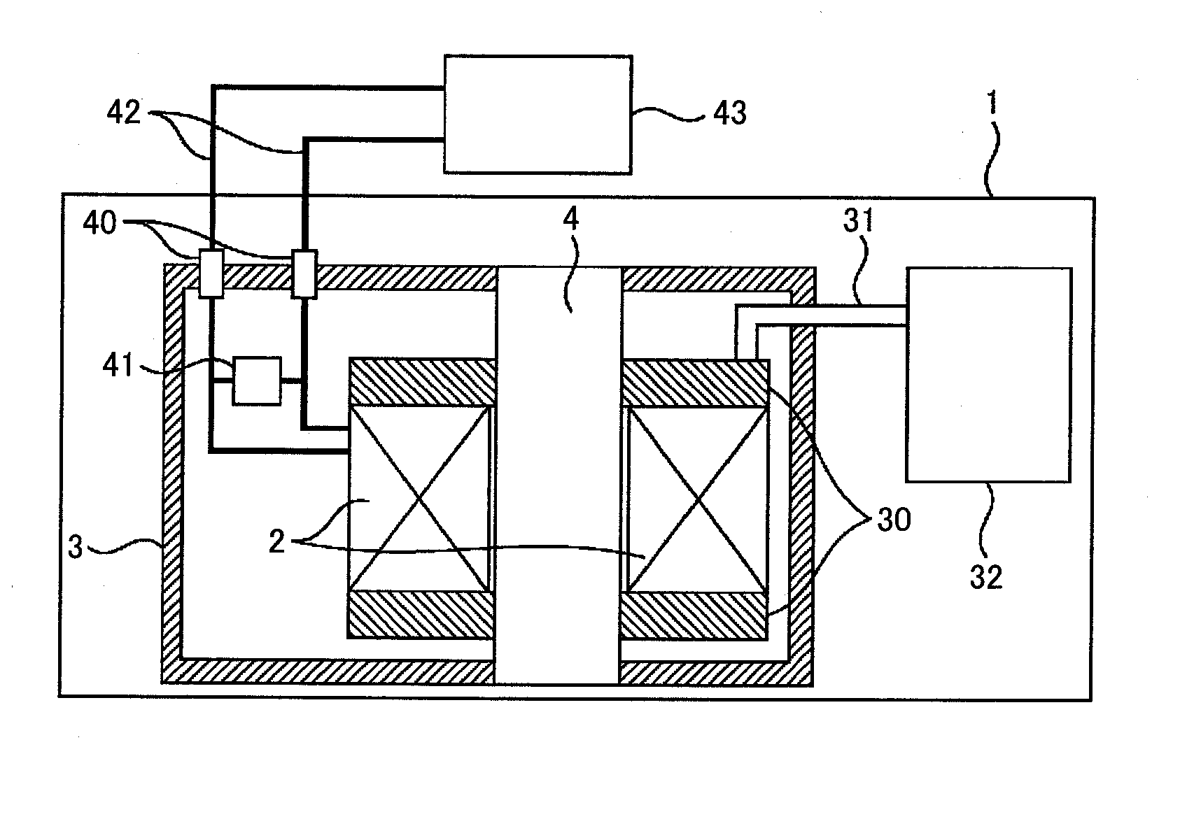
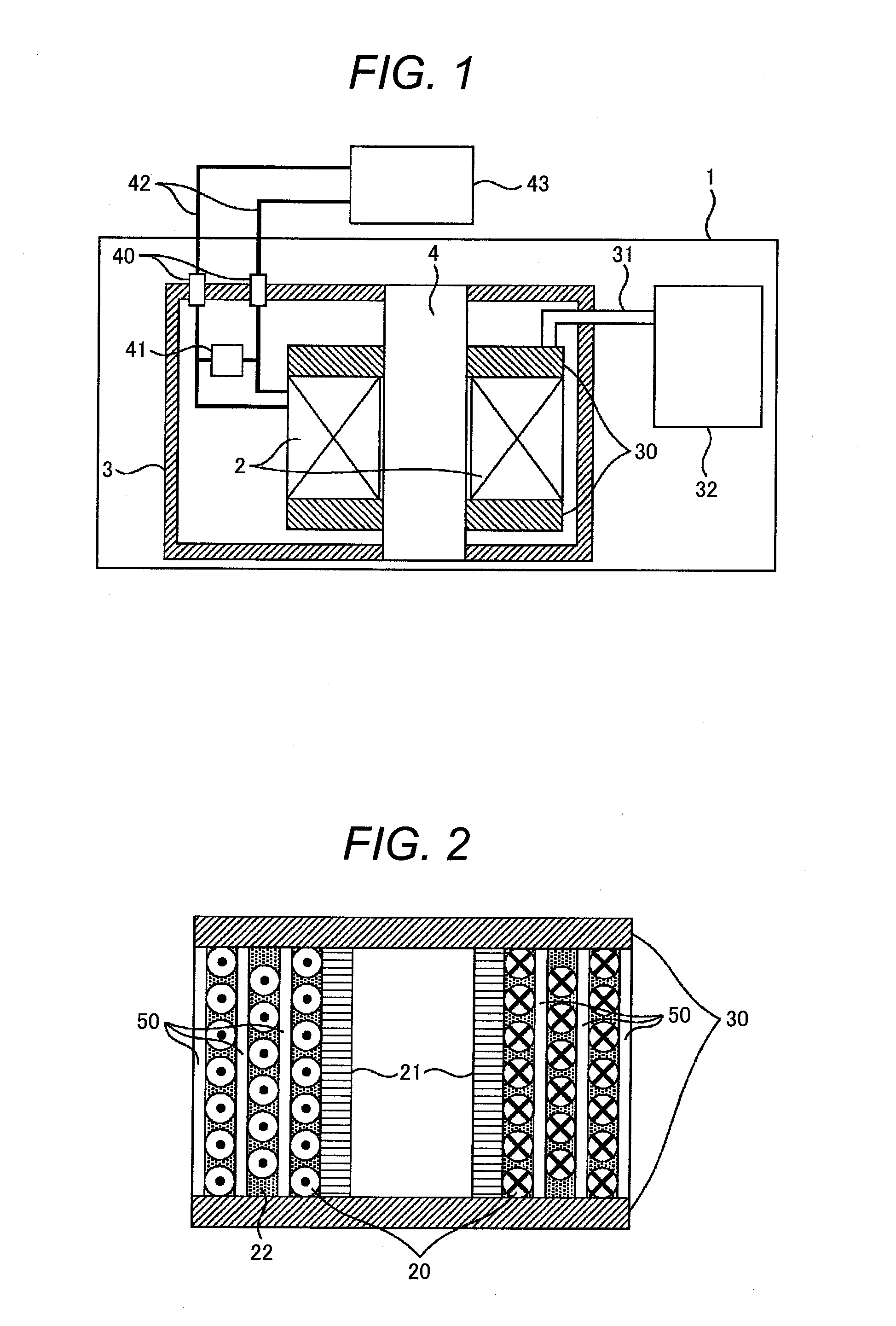
[0032]FIG. 1 is a schematic illustration showing a cross sectional view of an exemplary configuration of a superconducting magnet according to the present invention. As shown in FIG. 1, a superconducting magnet 1 of the invention includes a superconducting coil 2. The superconducting coil 2 is contained in a heat insulating container 3. The heat insulating container 3 includes a hollow cylinder 4 that extends through the axial bore of the superconducting coil 2. The superconducting coil 2 is in thermal contact with heat transfer plates 30, which are thermally connected to a refrigerator 32 external to the heat insulating container 3 by means of a cooling pipe 31.
[0033]In this manner, the superconducting coil 2 is cooled to below the operating temperature of the magnet 1 by the refrigerator 32.
[0034]Both ends of the superconducting coil 2 are electrically connected to respective current ports 40. A persistent current switch 41 is connected between the current ports 40...
second embodiment
of the Invention
[0053]FIG. 7 is a schematic illustration showing an enlarged cross sectional view of an exemplary arrangement of a superconducting coil wire and a metallic member of a current and heat conducting portion according to a second embodiment of the invention. As illustrated in FIG. 7, a current and heat conducting portion 50′ of the second embodiment includes an insulation layer 51 and a metallic filler 55 (as a metallic member) having good heat conductance. Multiple superconducting coil wires 20 are bundled. The space among the superconducting coil wires 20 in the bundle is filled with the metallic filler 55 having good heat conductance. Thus, the superconducting coil wires 20 in the bundle are electrically and thermally sufficiently connected to one another.
[0054]In FIG. 7, the bundle contains two layers of superconducting coil wires 20, but may contain one layer or more than two layers. The bundle of superconducting coil wires 20 is covered with the insulation layer 51...
third embodiment
of the Invention
[0057]FIG. 8 is a schematic illustration showing an enlarged cross sectional view of an exemplary arrangement of a superconducting coil wire and a metallic member of a current and heat conducting portion according to a third embodiment of the invention. As shown in FIG. 8, a current and heat conducting portion 50″ of the third embodiment includes an insulation layer 51 and a metal layer 56 (as a metallic member) having good heat conductance. Multiple superconducting coil wires 20 are bundled. The bundle of the superconducting coil wires 20 is surrounded by the metal layer 56 having good heat conductance. Thus, the superconducting coil wires 20 in the bundle are electrically and thermally sufficiently connected to one another. The metal layer 56 is further surrounded by the insulation layer 51, and therefore each turn of the bundle is electrically insulated from the neighboring turns of the bundle.
[0058]In FIG. 8, the bundle contains two layers of superconducting coil...
PUM
| Property | Measurement | Unit |
|---|---|---|
| absolute temperature | aaaaa | aaaaa |
| critical temperature | aaaaa | aaaaa |
| critical temperature | aaaaa | aaaaa |
Abstract
Description
Claims
Application Information
 - R&D
- Intellectual Property
- Life Sciences
- Materials
- Tech Scout
- Unparalleled Data Quality
- Higher Quality Content
- 60% Fewer Hallucinations
Browse by: Latest US Patents, China's latest patents, Technical Efficacy Thesaurus, Application Domain, Technology Topic, Popular Technical Reports.
© 2025 PatSnap. All rights reserved.Legal|Privacy policy|Modern Slavery Act Transparency Statement|Sitemap|About US| Contact US: help@patsnap.com


