Garden waterbed

a technology for waterbeds and plants, applied in the field of garden waterbeds, can solve the problems of high dislocation, add obstructions to the environment where laborers are working, and still dislodge objects from the outer edges, so as to maximize the productivity of each individual plant, increase yield, and add to the end cost of plants/crops

Inactive Publication Date: 2011-10-27
CARTER RICHARD C +1
View PDF2 Cites 14 Cited by
  • Summary
  • Abstract
  • Description
  • Claims
  • Application Information

AI Technical Summary

Benefits of technology

[0008]Members of the plant kingdom are sensitive to the environments in which they are grown. Members of this group include; woody and herbaceous, biennial, annual, and perennial plants whose flowers, bulbs, fruit, leaves, roots, stems, and tubers are used as food or for ornamental purposes. It is known that elongating the growing season for plants and crops will provide an opportunity to increase yields. Various devices have been used to protect plants and crops during their initial stages of growth in the early spring, or from harsh temperatures and frost in the autumn. Some start their seedlings in a greenhouse, thus controlling the environment and protecting the plant from harsh environmental conditions until late spring. Considerably adding to the end cost of the plant / crop, produce, fruit, or blossoms. Efforts to combat the colder conditions have been made by covering the plant with burlap, straw, or leaves in anticipation of a frost or snow. The global competition of produce markets makes it essential to maximize the productivity of each individual plant which is grown, and to increase the duration of the growing season, despite adverse climatic conditions. Still others have patents suggesting the use of thermally protective devices with plural fluid filled compartments. (U.S. Pat. No. 4,821,453 James B. Morehead April 1989) (Brittain U.S. Pat. No. 4,267,665 Wollace et al May 1981)
[0009]A difficulty has been observed with the inventions of the type suggested by the present invention in that the use of numerous devices need to be procured to support numerous plants. Essentially, each of the aforementioned inventions will only provide ample growing space for a single plant or crop. Increasing the number of devices raises the amount of labor involved with initial implementation, maintenance, and removal. Single plant devices also increase the amount of overhead.
[0010]U.S. Pat. No. 4,071,974 Tripp February 1978 offers an attempt to protect multiple numbers of plants from frost by harnessing thermal energy gained from the placement of a water filled sleeve next to plants. It offers thermal protection by covering the soil adjacent to growing plants. The use of one of these devices would offer thermal protection to only one side of the plant. Two devices, placed both adjacent and parallel to the plant are shown in prior art. This design limits the degree of thermal protection to just two sides of the plant, leaving the plant unprotected on two sides.
[0011]The aforementioned device would require multiple devices to offer limited thermal protection to each row of plants. The strip between the two devices, where the plants are rooted, is open and vulnerable to frost. The open gap between the two devices also allows an avenue for weeds and competitive plants to grow, offering no protection from competitive species where they are intrinsically most vulnerable, close to the roots and base. The previous art offers the use of multiple devices for protection of a single row of plants, multiple devices increases costs and takes up and inadequate amounts of space, making the garden plot cumbersome and inadequate for workers to tend to the plants. The positioning the device adjacent to the plants, yet close enough to gain the benefit of the thermal energy, takes up the space essential for workers to freely move through the rows to tend to the plants.
[0012]Another limitation of this art is that the design will not work on slopes or steep ground. The design of the sleeve of comprising the thermal energy is not suitable for use on any sort of a slope. The device would be inadequate if the apparatus was placed horizontal to the slope of the gradient, following the contour. Once fluid capacity is reached, gravity would force the mass down hill. The fluid contained in the sleeve would act as a wheel and roll. The device would not be adequate if the apparatus was placed vertical to the slope of the gradient. While filling the apparatus, the lower portion of the device would experience tremendous pressure from the fluid higher up the gradient, while the uphill portion would have little thermal retaining mass. In either case the thermal mass would be inconsistent and not uniform. This device is not designed for use on a slope or hill and would typically tear of the end would come undone and release the thermal mass.
[0014]The present invention provides a self-supporting, thermally protective semi-enclosed weed barrier that enhances plant and crop growth. Formed of a single flexible tube, this device suppresses weed growth while simultaneously protecting multiple plants from adverse environmental factors including: wind, cold, and frost.

Problems solved by technology

Since these devices are simply laid on ground, they are highly prone to dislocation by wind, heavy rain, and animals.
This adds obstructions to the environment where laborers are working.
Extreme rains and winds can still dislodge these objects from the outer edges.
This method is quite labor intensive.
This action makes holes and tears in the protective device.
Over time these holes and tears enlarge, allowing sunlight to penetrate underneath the device, promoting further weed growth and further tearing.
These devices are not only time consuming to deploy, but typically can only be used once and are difficult to remove.
Dislocation of prior art devices is typically restricted through stakes of staples pushed through the material of the prior art to hold it to the soil.
This is imperative with the use of prior art to prevent dislocation, though laborious to install and remove.
First, wind may lift the outer edges of the fabric or cloth, causing the edges to fold back, bunch, or lifting the entire device.
Second, wind may enter the planting spaces and cause the device to lift up and shift position.
Considerably adding to the end cost of the plant / crop, produce, fruit, or blossoms.
Essentially, each of the aforementioned inventions will only provide ample growing space for a single plant or crop.
Increasing the number of devices raises the amount of labor involved with initial implementation, maintenance, and removal.
Single plant devices also increase the amount of overhead.
This design limits the degree of thermal protection to just two sides of the plant, leaving the plant unprotected on two sides.
The aforementioned device would require multiple devices to offer limited thermal protection to each row of plants.
The strip between the two devices, where the plants are rooted, is open and vulnerable to frost.
The open gap between the two devices also allows an avenue for weeds and competitive plants to grow, offering no protection from competitive species where they are intrinsically most vulnerable, close to the roots and base.
The previous art offers the use of multiple devices for protection of a single row of plants, multiple devices increases costs and takes up and inadequate amounts of space, making the garden plot cumbersome and inadequate for workers to tend to the plants.
Another limitation of this art is that the design will not work on slopes or steep ground.
The design of the sleeve of comprising the thermal energy is not suitable for use on any sort of a slope.
The device would be inadequate if the apparatus was placed horizontal to the slope of the gradient, following the contour.
The device would not be adequate if the apparatus was placed vertical to the slope of the gradient.
In either case the thermal mass would be inconsistent and not uniform.
This device is not designed for use on a slope or hill and would typically tear of the end would come undone and release the thermal mass.

Method used


Image

  • Garden waterbed
  • Garden waterbed
  • Garden waterbed

Examples


Embodiment Construction

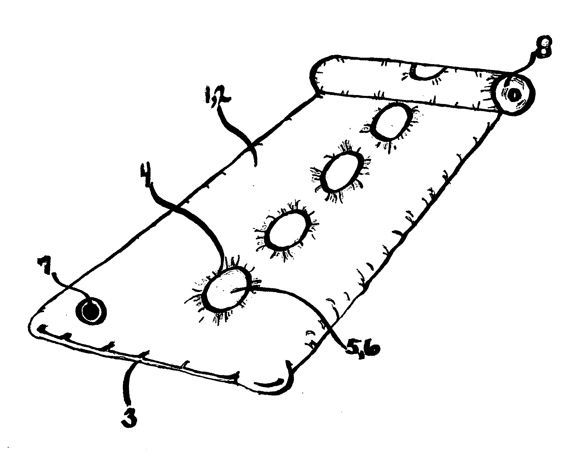
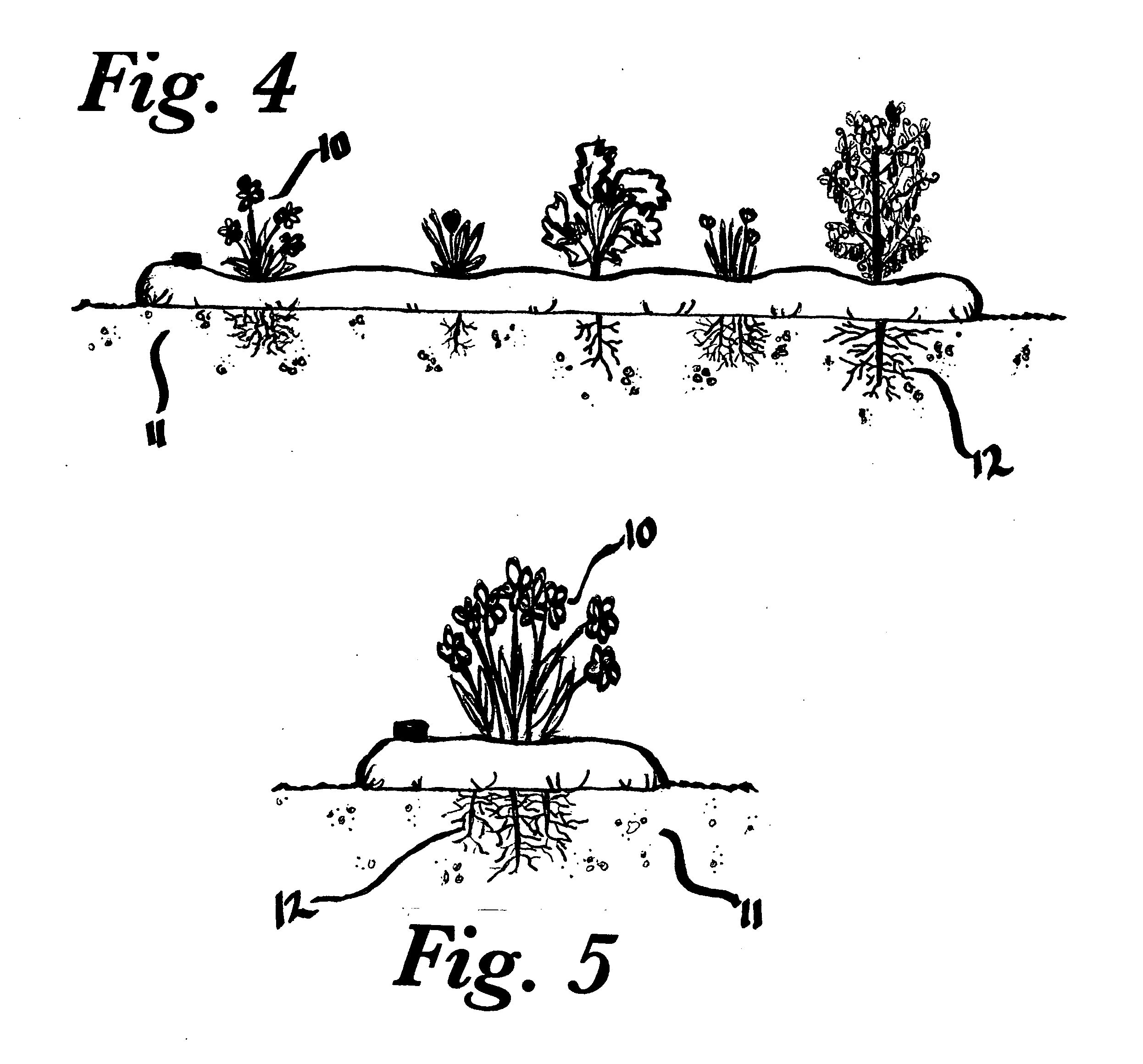
[0032]The basic idea of the thermally protective weed barrier in protecting plants enclosed by the barrier is to prevent competitive plant growth and increase temperatures surrounding the plants. Maximum thermal protection will be reached by filling the device to maximum capacity. The increased mass increases the potential thermal energy. This may prove to be beneficial in early spring or late fall, during periods of colder weather or when frost is eminent. However, maximum thermal protection may not be need during periods of warm weather. Since the amount of thermal energy is dependent upon the amount of fluid contained in the apparatus, the valve can be opened and fluid drained out to reach the desired amount of protection needed. The varying amount of thermal protection does not impact the viability of weed suppression.

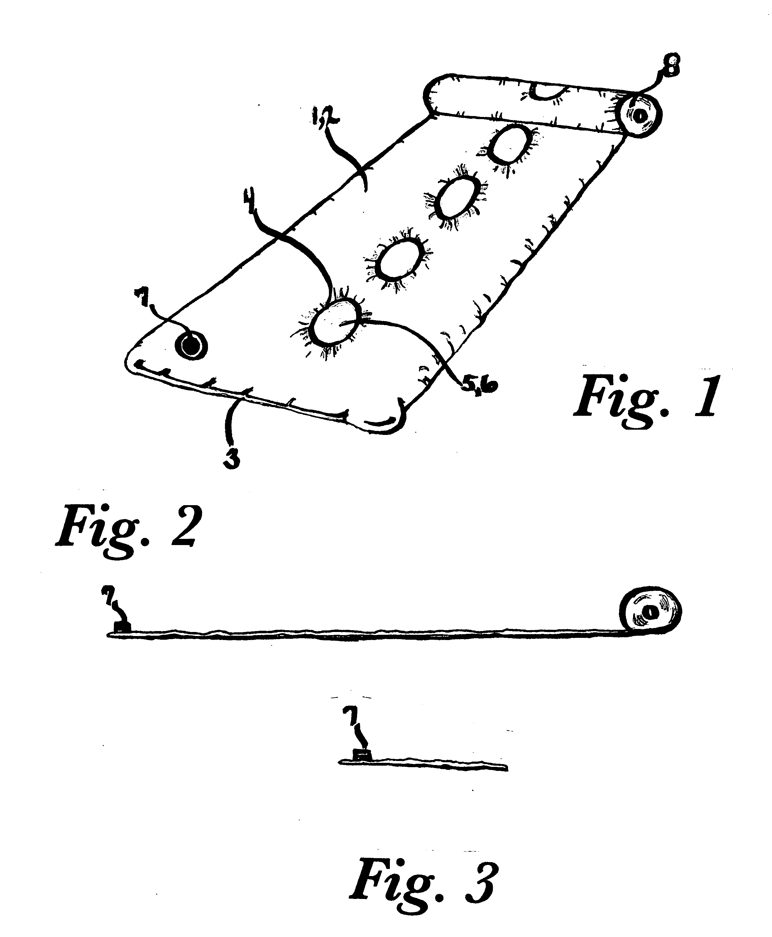
[0033]Referring to the drawings, a first embodiment of the invention is shown in FIG. 1, showing a self-supporting, thermally protective weed barrier, being genera...


PUM


Abstract

The Garden Waterbed is constructed of a durable tube of flexible UV protected material. The ends of the tube have been sealed, enabling it to hold water. Circular holes have been cut out and sealed down the center length of the tube, at regular intervals. A valve is installed at one end of the tube, allowing water to be filled into the large single chamber and hold it with a tight seal. There are multiple purposes of the Garden Waterbed. The water bed's intended use is; to be rolled out in a agriculture environment or garden area, to be filled with water, and to have plants buried in the soil within the growth units. The surrounding water increases the thermal mass surrounding the plants in the circular holes. The thermal mass absorbs the suns energy and increases soil temperature, thus increasing the growing season and boosting production. The opaque plastic stops sunlight from reaching the ground and eliminates weeds and undesirables from competing with your crop. At the same time insulating the ground and shading the soil, decreasing crop water consumption and increasing earthworm populations, increasing overall cleanliness of the subject grown, and increasing disease and insect infestation protection. The flexible design allows for quick and easy installation and roll away storage.

Description

BACKGROUND OF THE INVENTION[0001]1. Field of Invention[0002]The present invention is in the field of devices for gardening and agriculture. More particularly in the field of self supporting thermal protection and suppression of competitive vegetation.[0003]2. Description of Related Art[0004]Weed Suppression[0005]Plastics, fabrics, and landscape cloths have been used, in prior art, to aid in the control of weeds and stabilize tilled soils. When used in fields or garden environments, these devices greatly reduce maintenance otherwise required to prevent overgrowth of weeds. Since these devices are simply laid on ground, they are highly prone to dislocation by wind, heavy rain, and animals. This dislocation typically exposes underlying soil, permitting weeds to germinate and grow. Sometimes gardeners attempt to hold down the device by placing soil or rocks on the outer edges of the device. This adds obstructions to the environment where laborers are working. Extreme rains and winds can...

Claims


Application Information

Patent Timeline
Patent Type & Authority Applications(United States)
IPC IPC(8): A01G13/00A01G9/02
CPCA01G13/0268
Inventor CARTER, RICHARD C.CABRE, JAYNE ANDREA CARTER
Owner CARTER RICHARD C
Why Eureka
Try Eureka