Lightweight housing module and modular building

Inactive Publication Date: 2011-10-27
DALO CATHERINE
View PDF13 Cites 26 Cited by
  • Summary
  • Abstract
  • Description
  • Claims
  • Application Information

AI Technical Summary

Benefits of technology

[0045]Constituted as such, the panels 5 are arranged under the frame 3 pressing against a rail 11 (see FIG. 12) more preferably an extruded profile made of light alloy fixed to the ground, of which the straight section is in the general shape of an L, said rail 11 providing the seal between the panels 5 and the ground while preventing the panels 5 from directly resting on the ground in ord

Problems solved by technology

However, this type de module is not economical as they have a high operating cost especially for heating.
However, the standardization of these housing modules substantially limits the fantasy of the creation and, therefore, is not used for constructions tha

Method used


Image

  • Lightweight housing module and modular building
  • Lightweight housing module and modular building
  • Lightweight housing module and modular building

Examples


Embodiment Construction

[0006]The purpose of this invention is therefore to overcome the aforementioned disadvantages and to propose a lightweight housing module and a modular building constituted of a plurality of lightweight housing modules, each having high thermal insulation characteristics and being particularly simple to implement without having to call upon any high-capacity hoisting equipment.

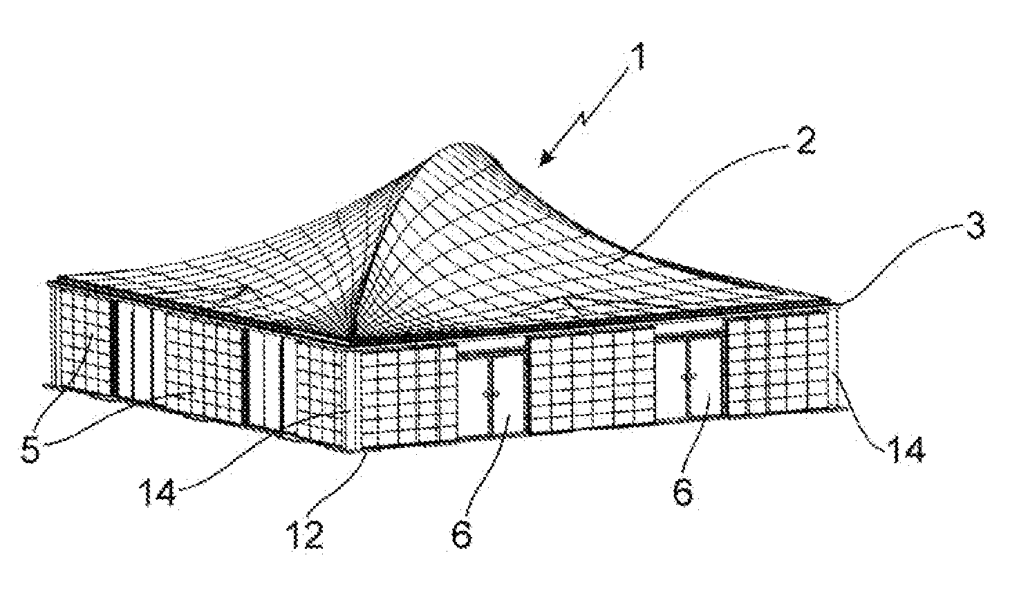
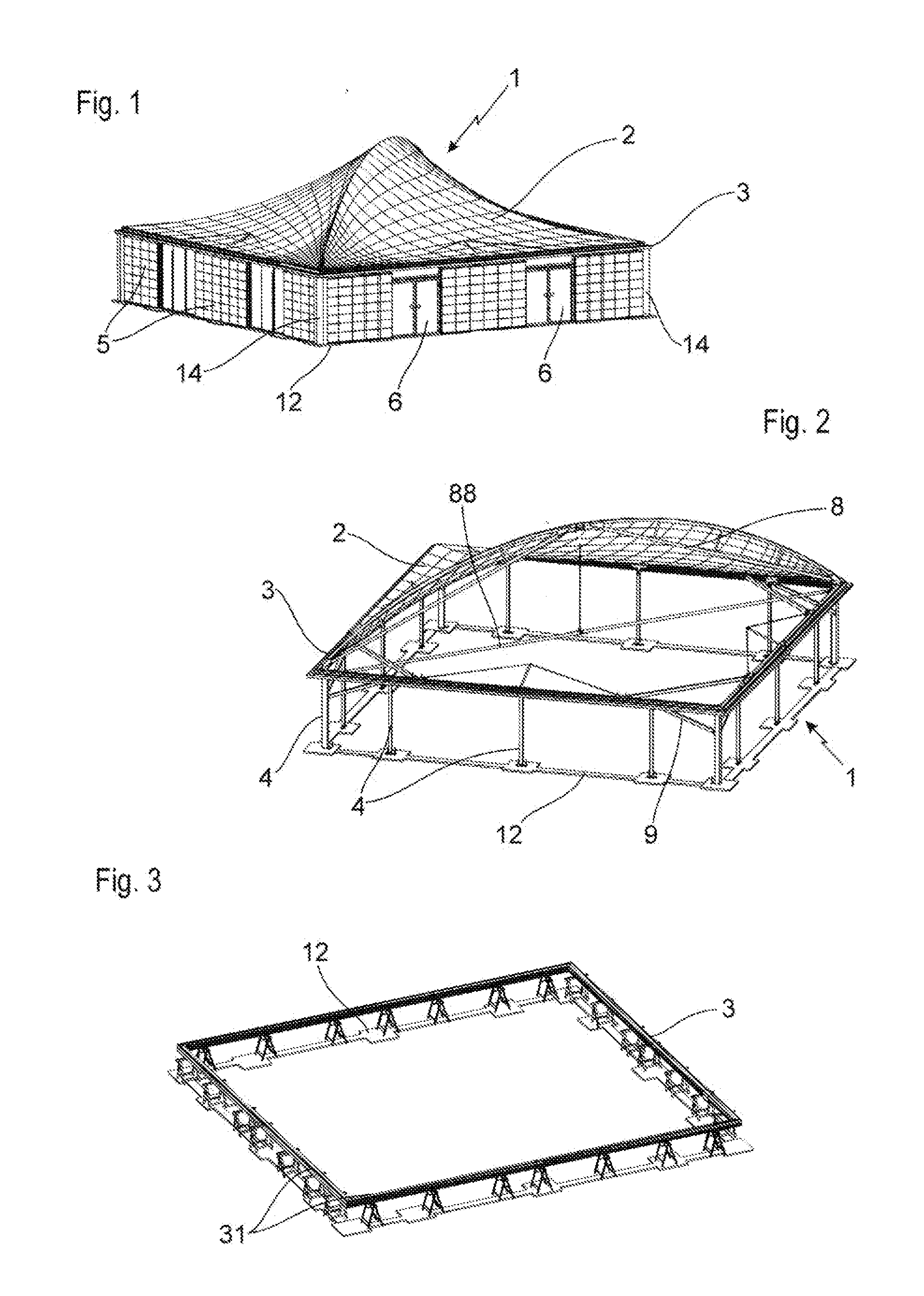
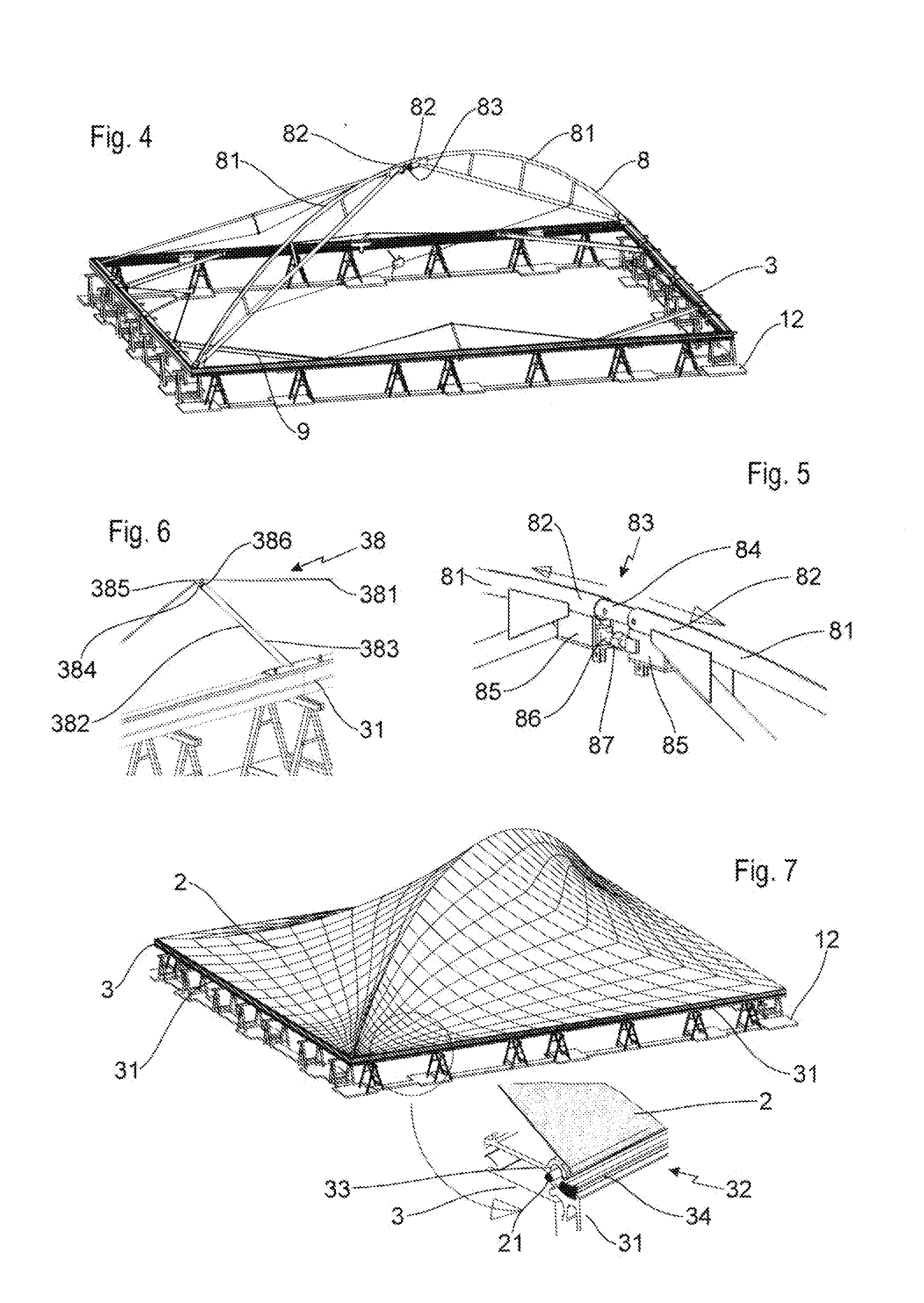
[0007]In accordance with the invention, it is therefore proposed a lightweight housing module comprising at least one stretched fabric intended to form the roof of said lightweight housing module and intended to be fixed along its lower peripheral edge on a rigid frame maintained at a distance from the ground by a plurality of lateral posts which are in turn intended to be fixed on the ground, remarkable in that it comprises a system for stretching said fabric arranged to be arranged entirely inside said lightweight housing module and able to stretch said fabric by pushing it upwards, vertical panels and / or op...


PUM


Abstract

This invention relates to a lightweight housing module comprising at least one stretched fabric intended to form the roof of said module and fixed along its lower edge on a rigid frame maintained at a distance from the ground by a plurality of lateral posts, remarkable in that it comprises vertical panels and/or opening frames in order to close in a substantially sealed manner its vertical facades and a false ceiling arranged in order to be arranged under said fabric inside said lightweight housing module and fixed to the frame. This invention also relates to a modular building remarkable in that it comprises a plurality of lightweight housing modules, according to the invention, arranged next to one another, and a system for sealing between the adjacent lightweight housing modules. This invention also relates to their method of assembly.

Description

TECHNICAL FIELD[0001]This invention relates to a lightweight housing module and a modular building constituted of a plurality of lightweight housing modules, as well as their respective method of assembly.PRIOR ART[0002]Lightweight housing modules are already known comprising a stretched fabric intended to form the roof of said module and conventionally fixed along its lower peripheral edge on a rigid frame maintained at a distance from the ground by a plurality of lateral posts which in turn are fixed on the ground. Said fabric can then be stretched by fixing its central portion to the upper end of a central mast then by pulling on the lower edge of said fabric via suitable means. The fabric can also be stretched by at least one arch subdivided into two semi-arches of which the lower ends each press against the rigid frame, and of which the upper ends are connected to one another by a device making it possible to separate said upper ends from one another in order to obtain, on the ...

Claims


Application Information

Patent Timeline
IPC IPC(8): E04H15/54E04D13/064
CPCE04B1/34315E04B1/76Y10S135/908E04H1/1205E04H15/18E04B7/14
Inventor DALO, CATHERINE
Owner DALO CATHERINE
Why Eureka
Try Eureka