Flow cytometer and flow cytometry

a flow cytometer and flow cytometry technology, applied in the direction of optical radiation measurement, fluorescence/phosphorescence, nuclear engineering, etc., can solve the problems of hardly recovering droplets and aerosol once attached to the sorting chamber, the risk of infection of workers including operators of cell sorters, and the biohazard of the sorting chamber

Inactive Publication Date: 2011-10-27
BAY BIOSCI
View PDF4 Cites 53 Cited by
  • Summary
  • Abstract
  • Description
  • Claims
  • Application Information

AI Technical Summary

Problems solved by technology

Thus, it has been reported that according to the conventional art, the sample cell particles might be carried over in the cell sorter and contaminated with the other liquid flow.
Also it has been concerned that when the cell particles to be sorted contain HIV virus or hepatitis virus, those harmful cell particles, which are exposed outside the cell sorter and the sorting chamber or suspended in the air, may cause the biological hazard.
However, although the cell sorter disclosed in the aforementioned prior art may aspirate some droplets and aerosol from the sorting block, it can hardly recover droplets and aerosol once attached on the sorting chamber.
Also according to the prior art, while the droplets and aerosol containing the infectious viruses attached on the sorting chamber may again be evaporated and suspended in the air, the cell sorter may recover them only during activation of the aspirator, but the infectious viruses may be suspended and diffused after deactivation of the aspirator, which brings risks of the infection to workers including operators of the cell sorter.
Thus, according to the prior art, the cell sorter cannot be used for the next sorting operation while the aspirator is being activated to aspirate the droplets and aerosol.
Further the above-mentioned cell sorter fails to even address the problem of the cell particles carried over or remained upstream the sorting chamber such as in a sample-liquid flow mechanism, a flow cell, and a strobe block, which may be contaminated in another liquid flow.

Method used


Image

  • Flow cytometer and flow cytometry
  • Flow cytometer and flow cytometry
  • Flow cytometer and flow cytometry

Examples


Embodiment Construction

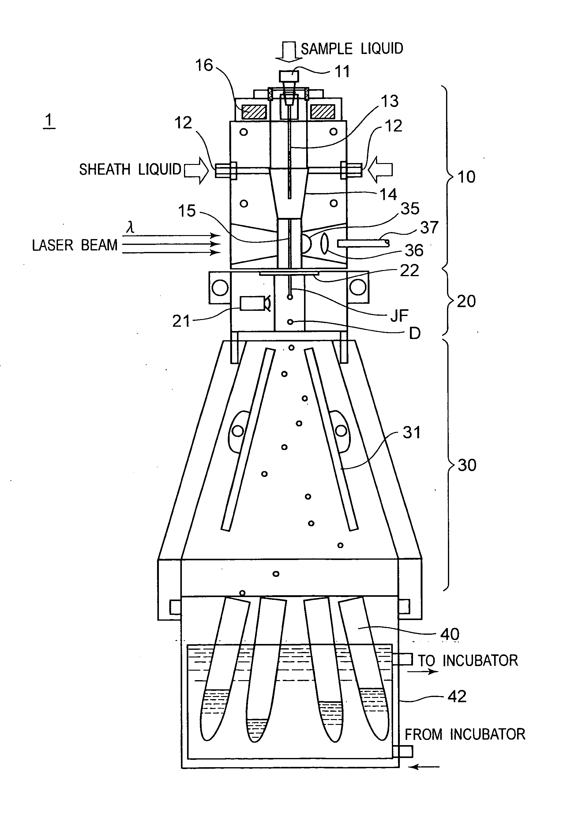
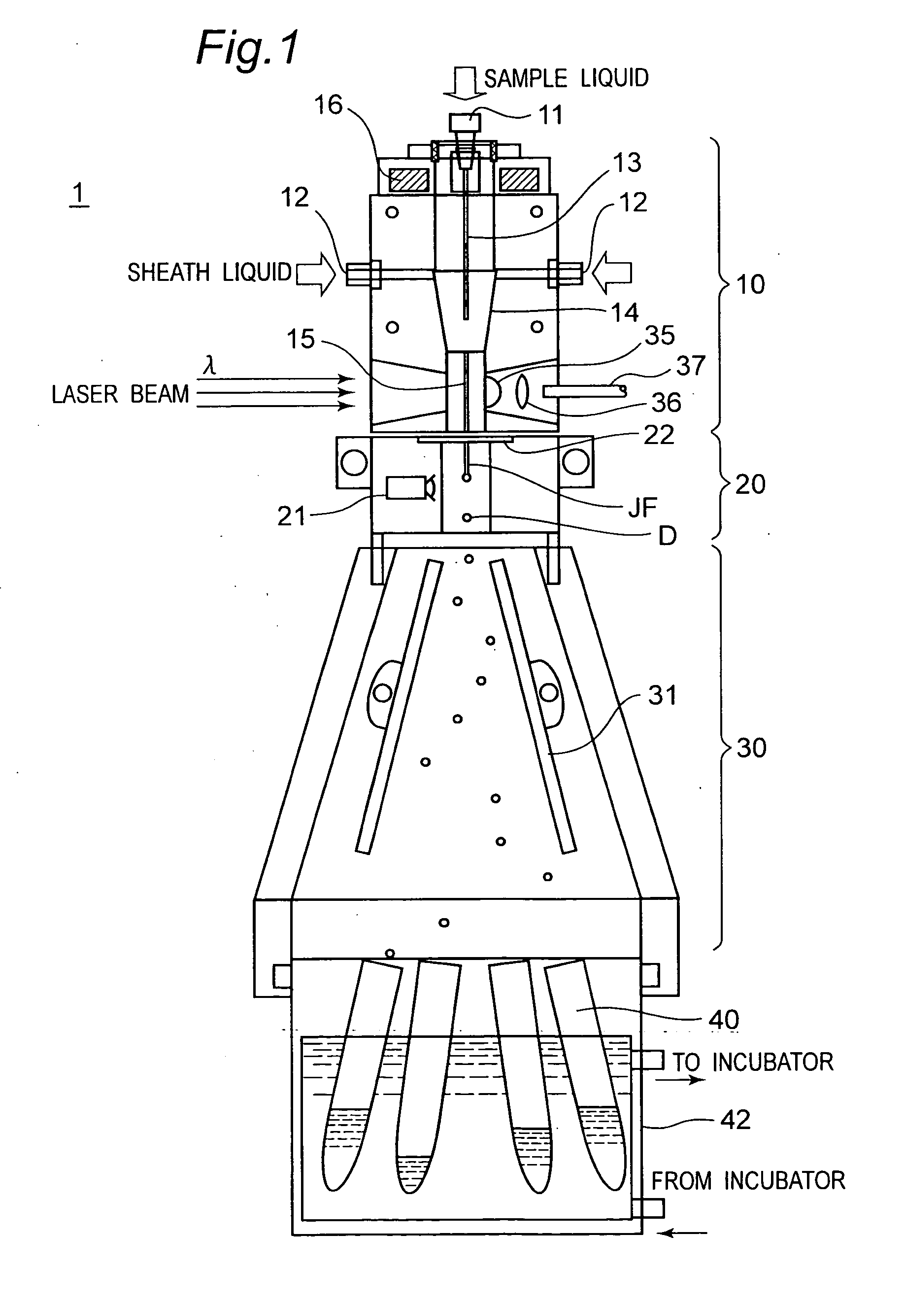
[0031]Referring to attached drawings, embodiments of a system for sorting biological particles contained in a liquid flow such as a cell sorter according to the present invention will be described herein. Although the cell sorter will be exemplarily illustrated herein for facilitating clear understandings of the present invention, it may be applied equally to a flow cytometer as well. In the description, a couple of terms for indicating the directions (for example, “upper” and “lower”, etc.) are conveniently used, it should not be interpreted that those terms limit the scope of the present invention.

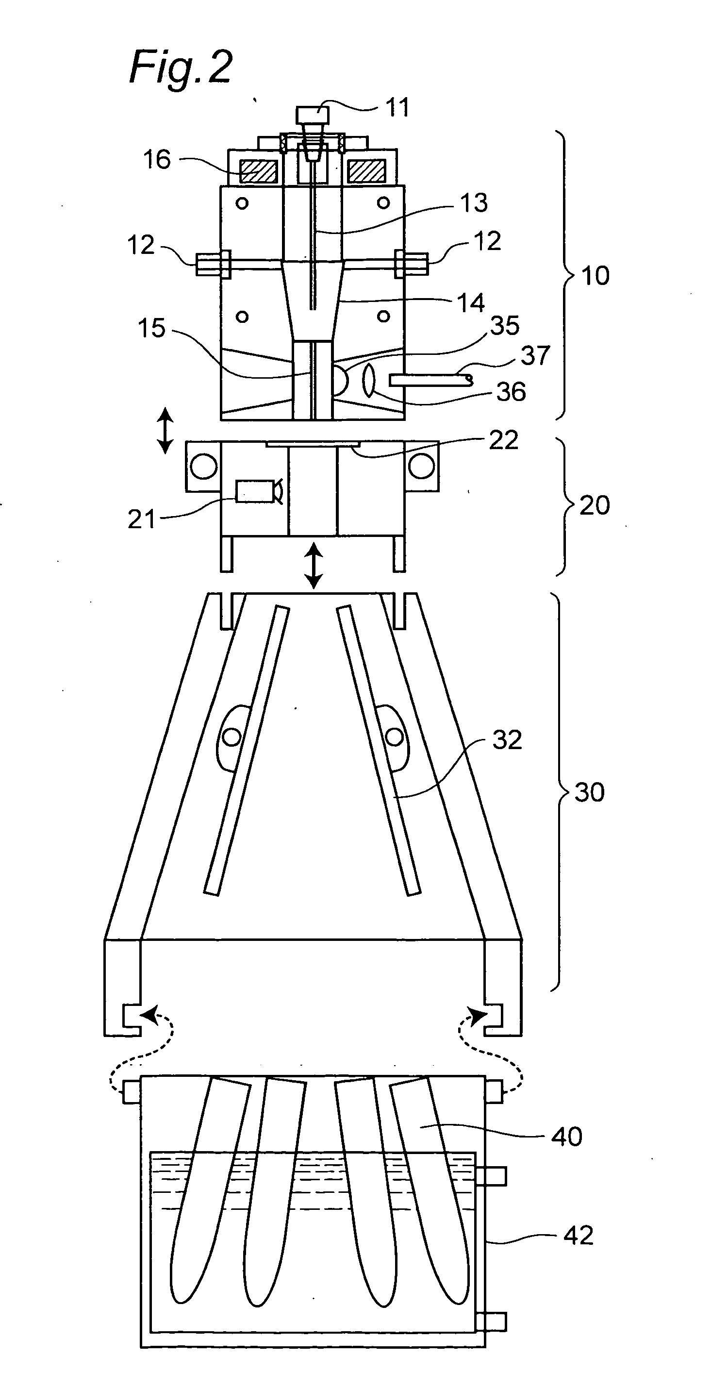
[0032]FIG. 1 is a schematic overall view of a cell sorter showing a general structure thereof according to one embodiment of the present invention, and FIG. 2 is an exploded view of a cell sorter according to one embodiment of the present invention, illustrating major components thereof. The cell sorter 1 generally comprises a flow-defining block 10, a strobe block 20, a sorting chamber ...


PUM

PropertyMeasurementUnit
open distanceaaaaaaaaaa
inner diameteraaaaaaaaaa
open distanceaaaaaaaaaa

Abstract

One embodiment of the present invention is to provide a system for sorting cell particles in a liquid flow, which comprises a flow-defining block including a flow chamber receiving a sample conduit and a flow cell having a flow channel. The system also comprises a strobe block including a imaging device for taking an image of a jet flow ejected from the flow-defining block and a plurality of droplets in a given image area. The flow-defining block and the strobe block are detachably connected each other. Further the strobe block includes a nozzle plate having a nozzle channel between a receiving end and a nozzle. The flow-defining block includes a discharge end opposite to the receiving end and a channel enlarged portion of which cross section taken along a predetermined plane perpendicular to a flow direction has an area increasing towards the discharge end. The discharge end and the receiving end have substantially the same open distance in the predetermined plane perpendicular to the flow direction.

Description

TECHNICAL FIELD[0001]The present invention relates to a flow cytometer and a flow cytometry, and in particular to the flow cytometer and the flow cytometry, which allows a series of steps of analyzing and sorting different cell particles within liquid flows, preventing cell particles in the previous liquid flow from being remaining in or contaminating the next liquid flow.BACKGROUND ART[0002]Recent rapid development of the biotechnology expands a demand of a flow cytometer and a cell sorter which are more commonly used in the various fields of medicine and biology for automatic analysis and fractionation of multiple cells.[0003]In general, the flow cytometer forms a stream of a sheath flow containing various cell particles aligned in line, which are collected from a living body (blood, etc.) and dyed with a fluorescent labeling reagent, and emits laser beam onto the stream of the cell particles to detect light excited by and / or scattered at the cell particles (i.e., forward-scattere...

Claims


Application Information

Patent Timeline
Patent Type & Authority Applications(United States)
IPC IPC(8): G01N27/453G01N21/64G01N21/00
CPCG01N15/14G01N2015/1406G01N2015/149
Inventor KANDA, MASAHIKO
Owner BAY BIOSCI
Why Eureka
Try Eureka