The present invention aims to at least partly overcome the above-mentioned disadvantages, or to provide a
usable alternative. In particular the invention aims to provide a
solenoid valve with which it is possible to predict a possible malfunctioning of the valve at an earlier stage such that it can be foreseen and prevented by proper maintenance.
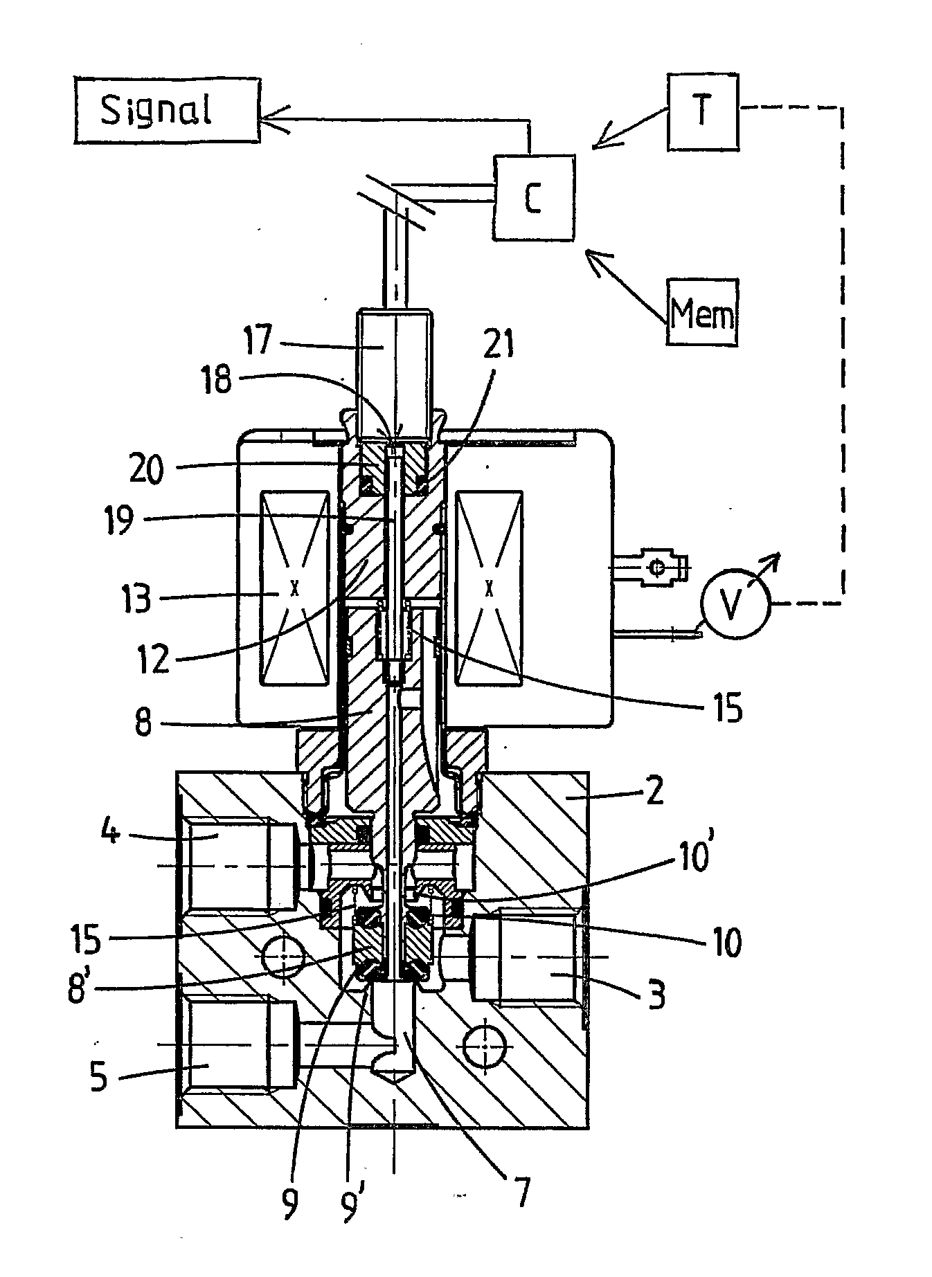
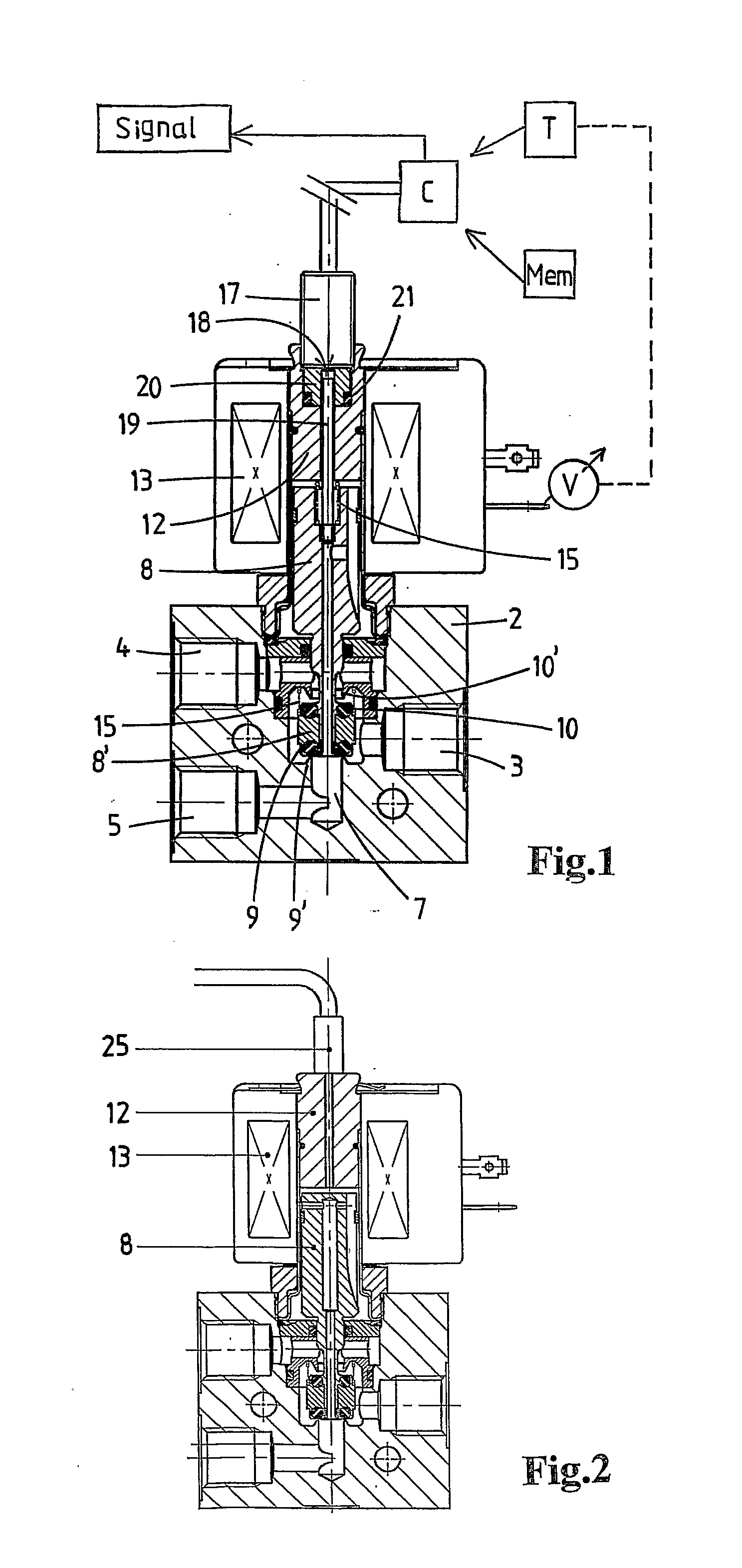
This aim is achieved by a solenoid valve according to the present invention. With this the valve comprises a housing having an axial bore which is in flow connection with at least one inlet and outlet port. A valve element is moveable to and fro in the axial direction of the bore. An electrical coil for generating a
magnetic field is provided for moving the valve element between a first (closed) end position and a second (open) end position. A
position sensor is present for detecting axial positions of the valve element inside the bore. According to the invention a
control unit is provided for determining
stroke, velocities and / or accelerations of the valve element in the axial direction of the bore as a function of the detected axial positions during movements of the valve element between its first and second end positions. The thus determined movement behaviour of the valve element can advantageously be used to give feedback of the performance of the solenoid valve to a user, controller, operator, or the like. The movement behaviour, in particular the maximum
stroke the valve element covers during a movement between its two end positions and / or the velocity pattern of the valve element during a movement between its two end positions and / or the acceleration pattern of the valve element during a movement between its two end positions, can be analyzed and provide the user, controller, operator, or the like with information about the health status and failure modus of the valve. This makes the valve
safer and more reliable. For example, it may lead to the conclusion that parts of the valve are damaged or are likely to get damaged soon or that movement of the valve is (partially) blocked or is likely to get blocked soon. The determined velocities and / or accelerations can for example say something about the friction of the valve element in the axial bore. Also they can give an indication of the condition of sealing elements of the valve, like O-rings. The maximum stroke can likewise say something about the condition of the sealing elements of the valve, like the O-rings. All in all the invention makes it possible to achieve a higher so-called
Safety Integrity Level (SIL) for a solenoid valve. In particular the invention to add diagnostic coverage about the condition of the valve and thus to provide a detection of the unknown chances for future failure in order to be able to anticipate such failure before it is actually happening, makes it possible to achieve a SIL4 instead of a SIL3 classification.
The
control unit comprises a memory with a set of references of stroke, velocities and / or accelerations which are indicative for a proper functioning of the valve and for a future malfunctioning of the valve. The control unit can then compare the determined stroke, velocities and / or accelerations with the reference stroke, velocities and / or accelerations, and take appropriate action. This appropriate action includes sending out a feedback
signal about failure modus and health status towards a user, controller, operator, or the like. In the case that the determined stroke, velocities and / or accelerations are outside an allowed range of the set of reference stroke, velocities and / or accelerations the feedback
signal may be sent out. For example the solenoid valve can give a
signal when the friction gets too high and thus the velocity and / or acceleration gets too low. An opening or closing velocity which is too high or low, may indicate a future failure of a spring of the valve. Another example is that if the valve is opening too slow, it may be an indication of the coil being too weak, for example because of too high temperature. This enlarges the risk of short-circuit. In those cases the valve needs maintenance, in particular that an element of the valve is likely to get damaged soon and needs to be replaced. With the sensor and corresponding electronic
system (control unit) the user is able to plan the maintenance and reduce the
downtime of a
plant for which the solenoid valve according to the invention is used.
Experience based methods, like Failure Mode and
Effect analysis and the like, can advantageously be used to fill the memory with a proper set of reference values.
Heuristic can help collecting
field data to select maintenance strategies. Thus an unknown upcoming failure can be changed into a predicted known failure. The present invention makes it possible to monitor the condition of the valve during its entire life-time. From the
field data it may follow that the characteristics of the valve change during its life-time. A valve which has been operated 10,000 times may have different operating behaviour than for example a valve which has been operated 100,000 times. This information can also be used as input for the memory and can be delivered together with the valve to a
maintenance system of a
plant. The control unit can then be designed such that after a specific number of operations and / or certain life-time, it switches to another set of reference values with which the determined stroke, velocities and / or accelerations as a function of the detected axial positions need to be compared.
In an embodiment, the set of reference values is specifically determined for an individual valve. By measuring a specific valve in the factory it is advantageously possible to determine its characteristic behaviour conditions and use them for choosing a proper set of reference values to fill up the memory of that particular valve with.
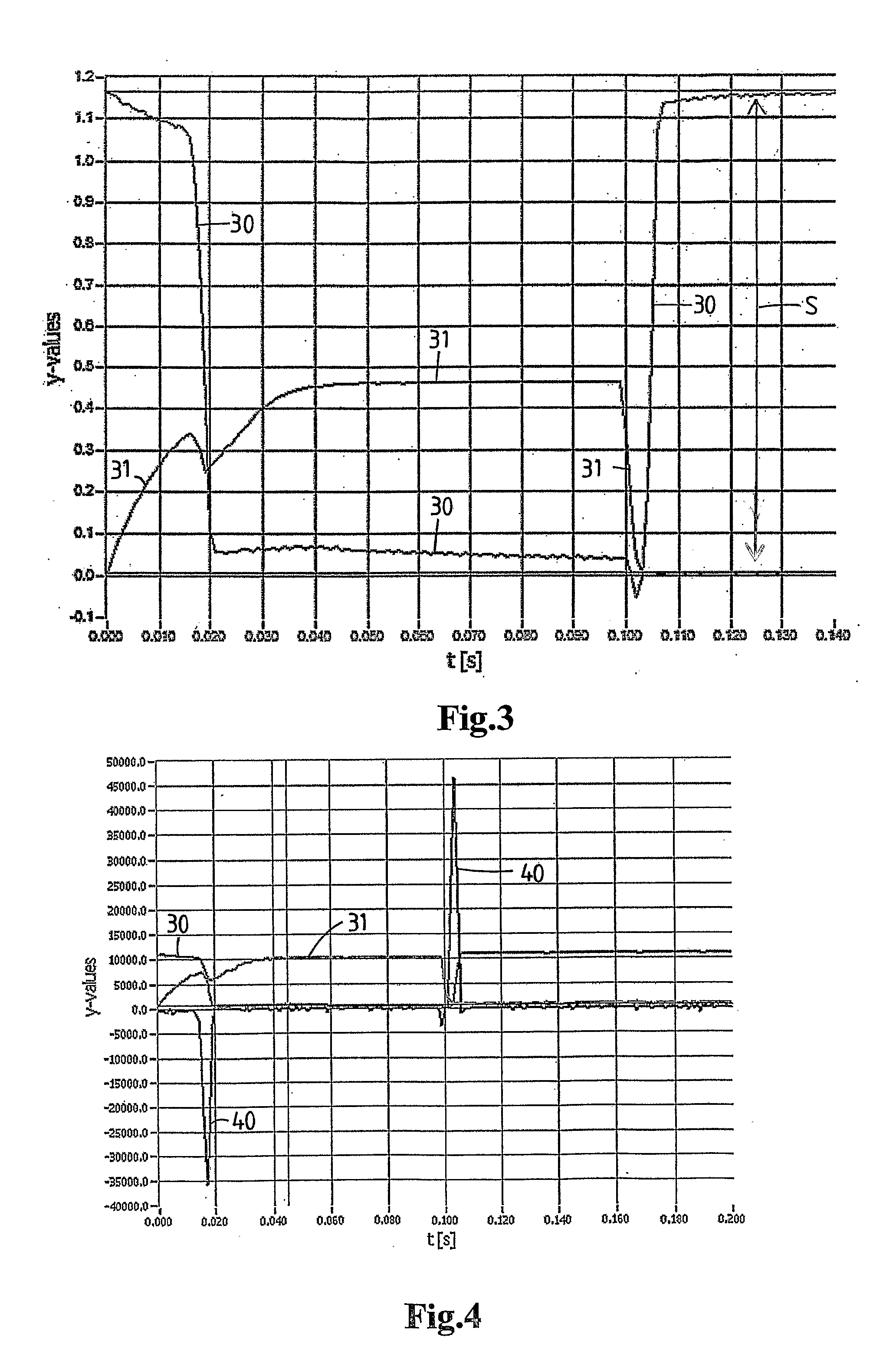
The stroke, velocities and / or accelerations may be monitored directly. Preferably however the control unit comprises a
timer for measuring time as a function of the detected axial positions of the valve element during a movement starting at its first towards its second end position or vice versa. The control unit is then designed for determining the velocities and / or accelerations by differentiating the detected positions against the measured time. By detecting the position (y) of the valve element as a function of the time (t), the velocity (y′=v) and / or acceleration (y″=a) can be obtained by differentiation (one time for velocity and two times for acceleration). This construction with the
timer is a simple and cheap solution. It has the
advantage that the
position sensor is used efficiently, not only to give position indications, but indirectly also to give the desired velocity and / or acceleration patterns.

