Vaporizing or atomizing of electrically charged droplets

a technology of electrically charged droplets and atomization, which is applied in the field of vaporizing apparatus and vaporizing method, can solve the problems of scorching or clogging the wall, difficult to achieve rapid vaporization,

Inactive Publication Date: 2011-10-27
VEECO ALD
View PDF6 Cites 22 Cited by
  • Summary
  • Abstract
  • Description
  • Claims
  • Application Information

AI Technical Summary

Benefits of technology

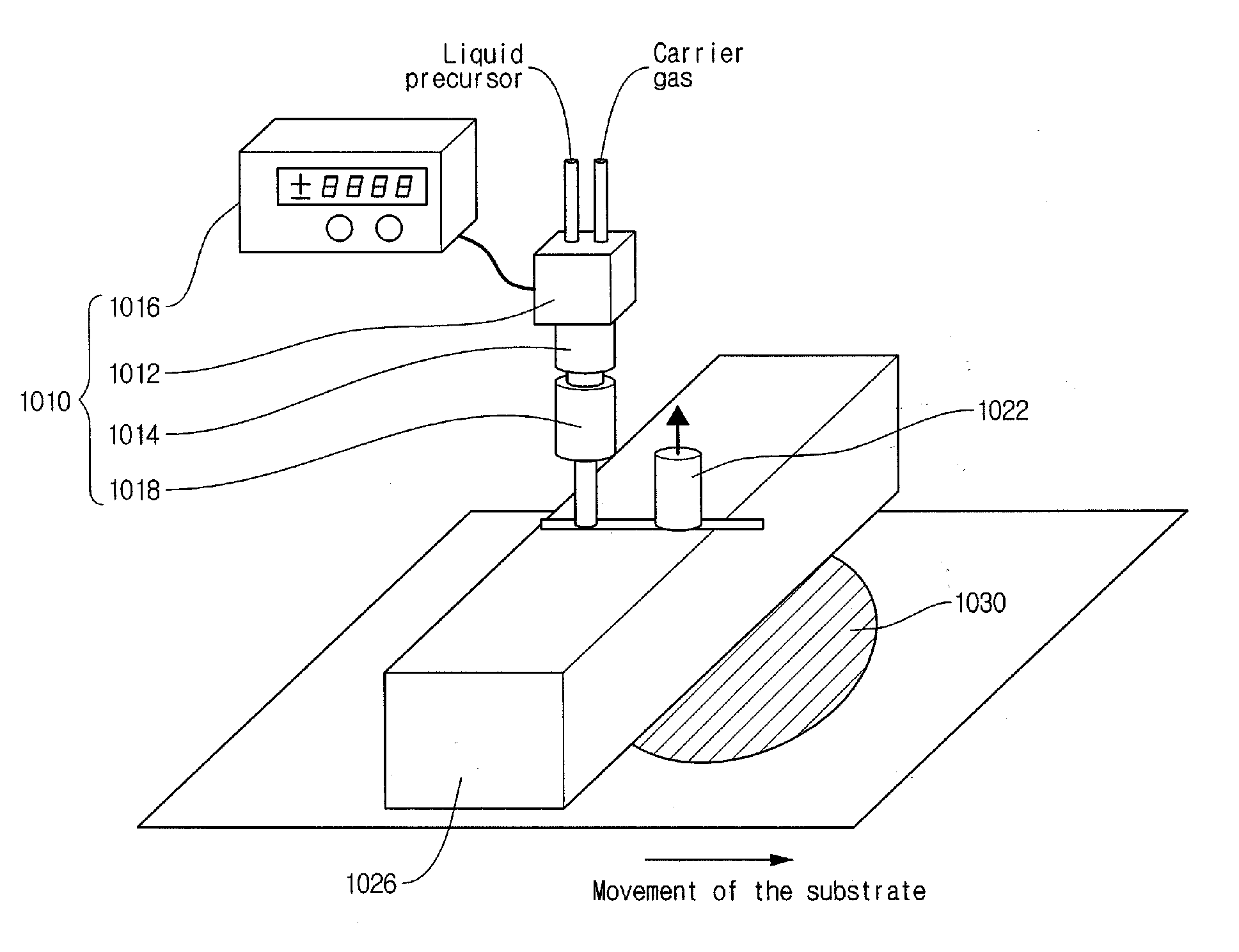
[0011]Embodiments relate to forming droplets of small size by electrically charging the droplets. Liquid is injected into a nozzle that is connected to a voltage source. As the liquid passes through the nozzle, the liquid or droplets are electrically charged. When charges in a droplet exceed a threshold, the droplet divides into multiple droplets. Hence, droplets of smaller sizes are obtained at the nozzle by charging the droplets. Moreover, the droplets charged with the same polarity repel each other, resulting in more even and uniformly dispersed droplets.

Problems solved by technology

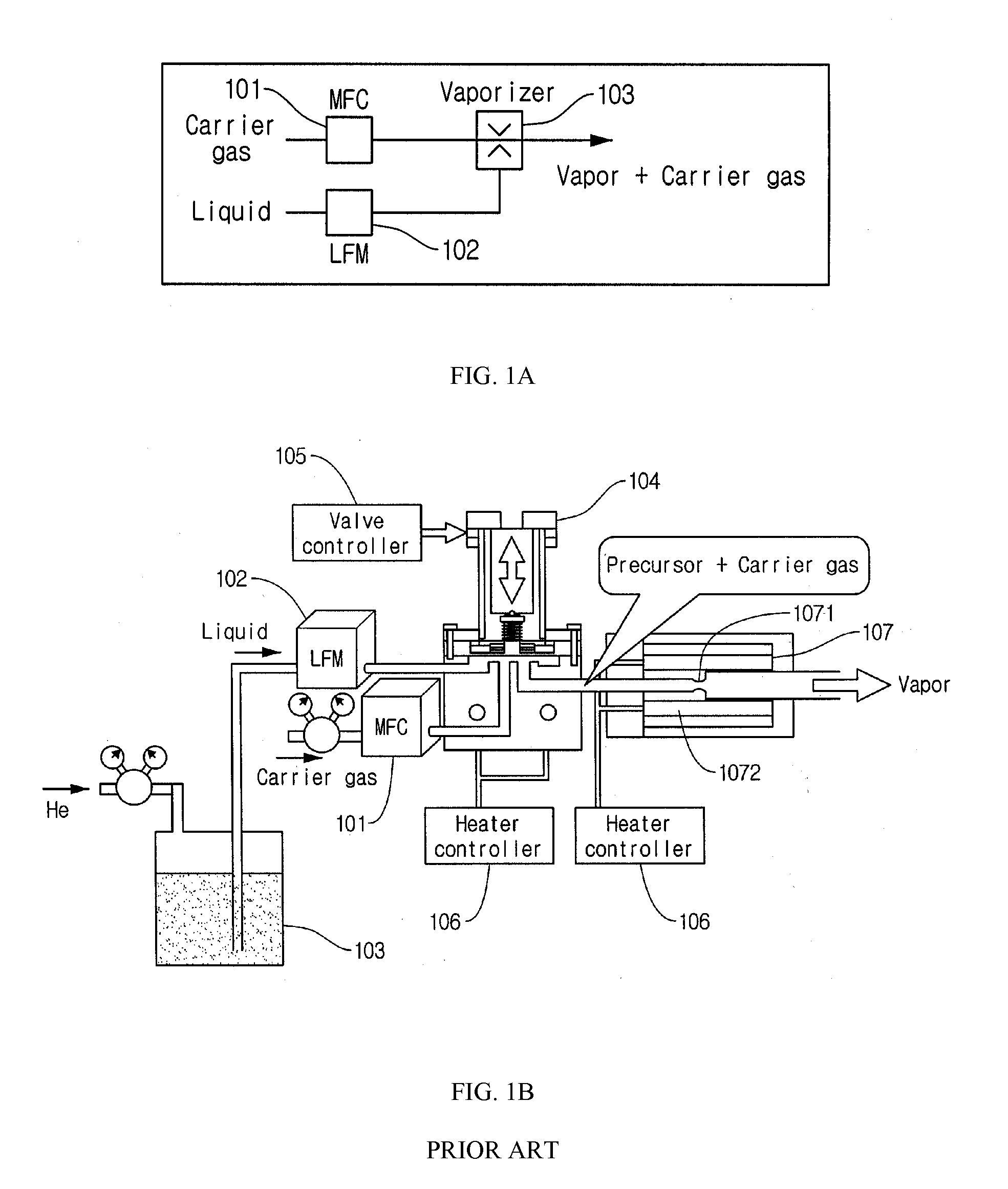
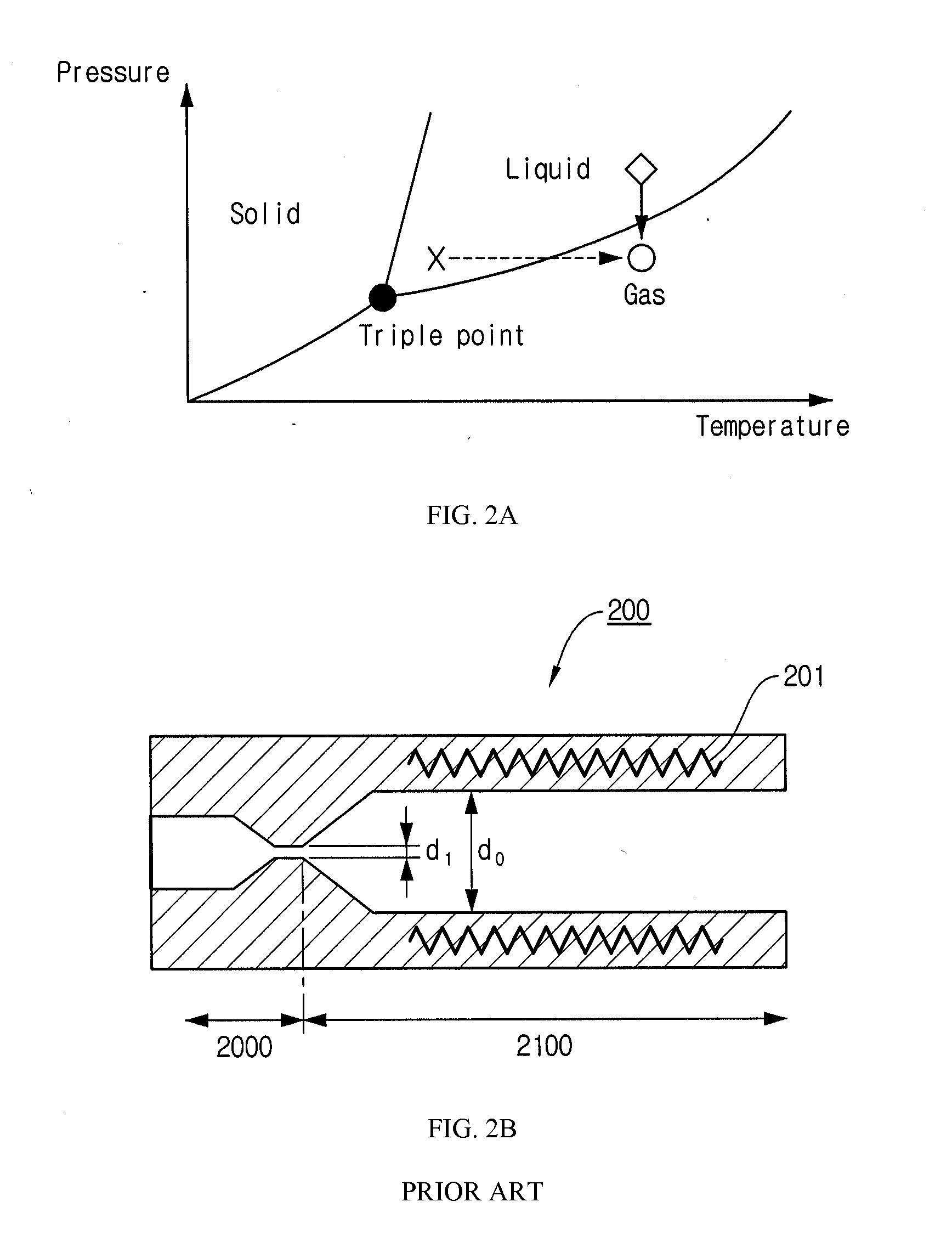
Increasing the temperature to change the phase may take an extended amount of time depending on the specific heat of the liquid fluid, and hence, rapid vaporization is difficult to achieve by increasing the temperature in certain types of liquid.
The vaporizer of FIG. 2B, however, has following disadvantages: (i) precursor with high viscosity or low vapor-pressure tend to clog the nozzle, (ii) the droplets formed in the atomizing stage are uneven in size, and hence, the vaporization stage produces some liquid droplets that are not vaporized, and (iii) the droplets may come in contact with the interior wall of the vaporizer and scorch or clog the wall.

Method used


Image

  • Vaporizing or atomizing of electrically charged droplets
  • Vaporizing or atomizing of electrically charged droplets
  • Vaporizing or atomizing of electrically charged droplets

Examples


Embodiment Construction

[0028]Embodiments are described herein with reference to the accompanying drawings. Principles disclosed herein may, however, be embodied in many different forms and should not be construed as being limited to the embodiments set forth herein. In the description, details of well-known features and techniques may be omitted to avoid unnecessarily obscuring the features of the embodiments.

[0029]The terminology used herein is for the purpose of describing particular exemplary embodiments only and is not intended to be limiting of this disclosure. As used herein, the singular forms “a”, “an” and “the” are intended to include the plural forms as well, unless the context clearly indicates otherwise. Furthermore, the use of the terms a, an, etc. does not denote a limitation of quantity, but rather denotes the presence of at least one of the referenced item. The use of the terms “first”, “second”, and the like does not imply any particular order, but they are included to identify individual...


PUM

PropertyMeasurementUnit
lengthaaaaaaaaaa
lengthaaaaaaaaaa
timeaaaaaaaaaa

Abstract

A vaporizing apparatus includes a chamber, a nozzle for dispersing a liquid into droplets, an electrode electrically isolated from the nozzle, and a heater for generating a vapor by applying heat to the droplets. The voltage source applies charges to the droplets by applying a voltage between the nozzle and the electrode. The vaporizing apparatus may be used to devices that deposit organic or inorganic thin films by chemical vapor deposition and / or atomic layer deposition processes, devices for supplying precursor materials that are deposited to form a thin film in organic light emitting diodes, devices that supply organic or inorganic precursor materials for encapsulation, and devices for supplying organic or inorganic polymer.

Description

CROSS-REFERENCE TO RELATED APPLICATION[0001]This application claims priority under 35 U.S.C. §119(e) to co-pending U.S. Provisional Patent Application No. 61 / 328,512, filed on Apr. 27, 2010, which is incorporated by reference herein in its entirety.BACKGROUND[0002]1. Field of Art[0003]The present invention relates to a vaporizing apparatus and a vaporizing method, more particularly to an apparatus and a method for vaporizing liquid for use in semiconductor fabrication processes.[0004]2. Description of the Related Art[0005]High performance fluid delivery systems are employed in semiconductor manufacturing processes. Such fluid delivery systems are designed to precisely dispense fluids that are hazardous and / or expensive. For example, in semiconductor fabrication processes, various stages such as low pressure chemical vapor deposition (LPCVD), oxidation, plasma enhanced chemical vapor deposition (PECVD), and atomic layer deposition (ALD) require corrosive precursors such as boron, sil...

Claims


Application Information

Patent Timeline
Patent Type & Authority Applications(United States)
IPC IPC(8): C23C16/44B05C11/00H05B3/03B05D1/00B05D1/32B05C5/00B05B1/00
CPCB05B5/043C23C16/45551C23C16/4486B05B5/001C23C16/44C23C16/448H01L21/20H01L21/0262
Inventor LEE, SANG IN
Owner VEECO ALD
Why Eureka
Try Eureka