Driving support apparatus of vehicle

a technology of driving support and vehicle, which is applied in the direction of steering initiation, vessel construction, instruments, etc., can solve the problems of difficult to realize the following target route by using a single steering mechanism, difficult to avoid the growth of uncomfortable feeling, and high probability of driving discomfort, so as to reduce the amount of steering angle reduction, stabilize the vehicle behavior, and increase the curvature of the target driving route

Inactive Publication Date: 2011-10-27
TOYOTA JIDOSHA KK
View PDF24 Cites 38 Cited by
  • Summary
  • Abstract
  • Description
  • Claims
  • Application Information

AI Technical Summary

Benefits of technology

[0034]If the driving condition as a concept including a vehicle operating condition, an environmental condition, and the like is different, the relation rotation angle necessary for the steering output shaft can be also different. According to this aspect, since the target relative rotation angle is set in accordance with the driving condition of the vehicle, it is possible to dispel the concern that the relative rotation of the steering output shaft destabilizes the vehicle behavior according to circumstances. A practical aspect associated with the selection of the driving condition of this type and the setting of the target relative rotation angle according to the selection may be in effect appropriately determined so as to stabilize the vehicle behavior to some extent in comparison with cases where this type of consideration is not made at all, from a viewpoint of motion dynamics or human dynamics, on the basis of experiments, experiences, theories, or simulations or the like in advance.
[0035]Incidentally, in this aspect, the second setting device may set the target relative rotation angle so as to reduce amount of reduction in the steering angle with an increase in curvature of the target driving route.
[0036]From a viewpoint on the driver's side, it is natural that the operation amount of the steering wheel increases with an increase in the curvature of the target driving route (i.e. inverse of the virtual radius of the target driving route, meaning that the target driving route is sharply curved with an increase in the curvature), and if the vehicle turns even if the steering angle is zero, it is hard to avoid the growth of the uncomfortable feeling. As described above, by setting the target relative rotation angle in accordance with the curvature of the target driving route, it is possible to perform the following for the target driving route, highly accurately, without making the driver feel uncomfortable.
[0037]Moreover, in this aspect, the second setting device may set the target relative rotation angle so as to reduce amount of reduction in the steering angle with an increase in speed of the vehicle.
[0038]If the speed of the vehicle (hereinafter referred to as a “vehicle speed” as occasion demands) is high, the lateral acceleration per unit steering angle is large. Therefore, if the amount of reduction in the steering angle is fixed to the vehicle speed, for example, the vehicle deviates from the target driving route in a high vehicle speed area and an actual steering direction could be opposite to the required steering direction. Alternatively, if such a trouble in the high vehicle speed area is avoided, the speed of the following for the target driving route will likely decrease in a low vehicle speed area. In other words, the stabilization of the vehicle behavior is prevented anyway. Therefore, by setting the target relative rotation angle in accordance with the vehicle speed, it is possible to perform the following for the target driving route, highly accurately, while suppressing the destabilization of the vehicle behavior.

Problems solved by technology

Moreover, in the configuration that the rudder angle can be changed by applying to the steering system an assist torque for assisting a steering torque given by a driver, the steering wheel is operated independently of the driver's will, and thus the driver can highly likely feel uncomfortable.
In other words, it is generally hard to realize the following for the target route by using a single steering mechanism.
Thus, if it is tried to realize the target rudder angle based on the curvature radius by using the electrically-assisted power steering apparatus, it is hardly possible to avoid the growth of the uncomfortable feeling.
Incidentally, further to the growth of the uncomfortable feeling, this type of uncomfortable feeling highly likely leads to the driver's unnecessary steering operation, so that it can cause the unstable vehicle behavior.
However, if the rudder angle per unit steering angle is increased as described above, the rudder angle significantly changes with respect to the steering operation performed by the driver's will, and the robustness of the vehicle decreases, resulting in the unstable vehicle behavior.
As described above, the conventional technology has such a technical problem that the vehicle behavior can be unstable when the vehicle is made to follow the target driving route.

Method used


Image

  • Driving support apparatus of vehicle
  • Driving support apparatus of vehicle
  • Driving support apparatus of vehicle

Examples


first embodiment

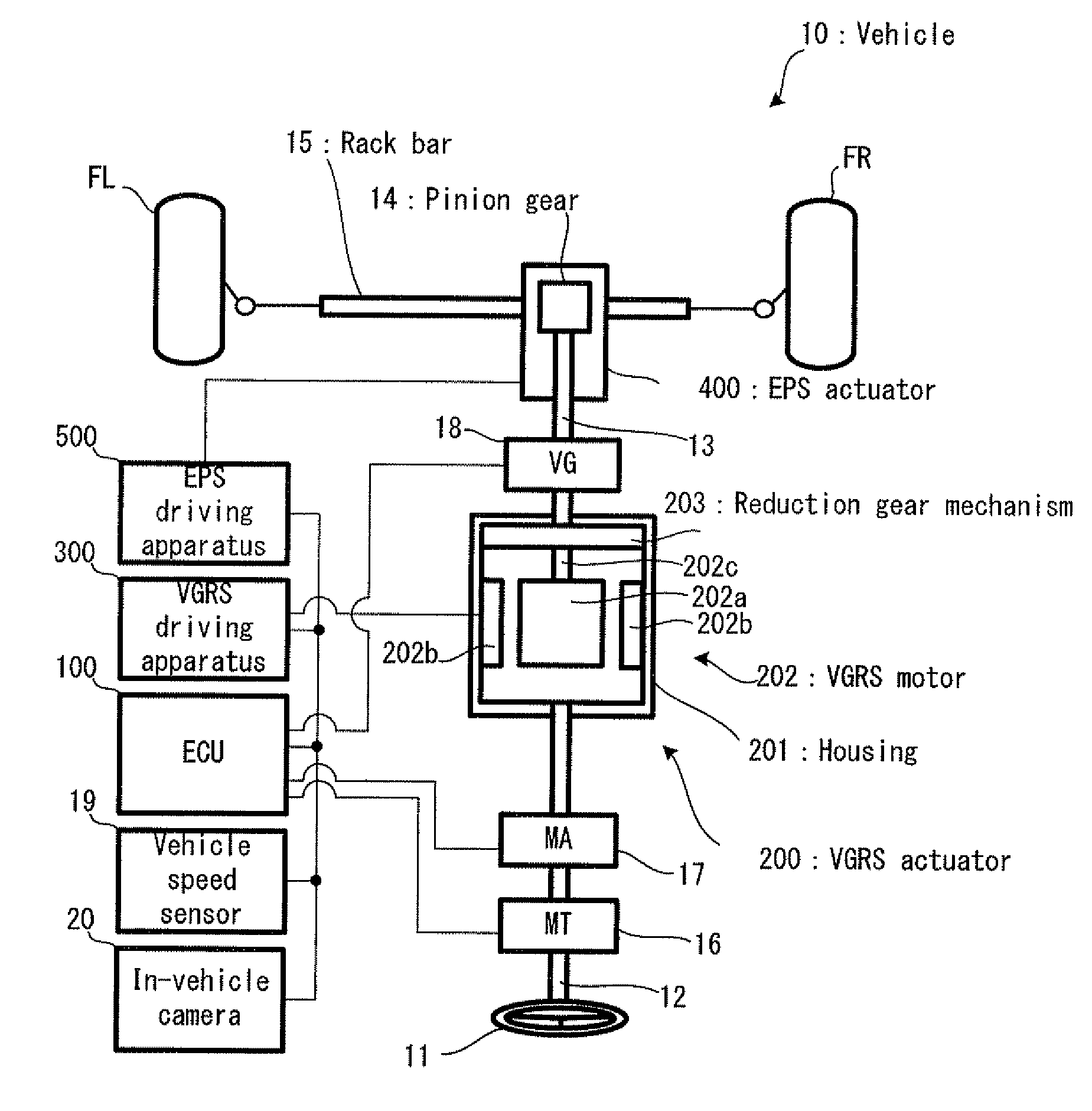
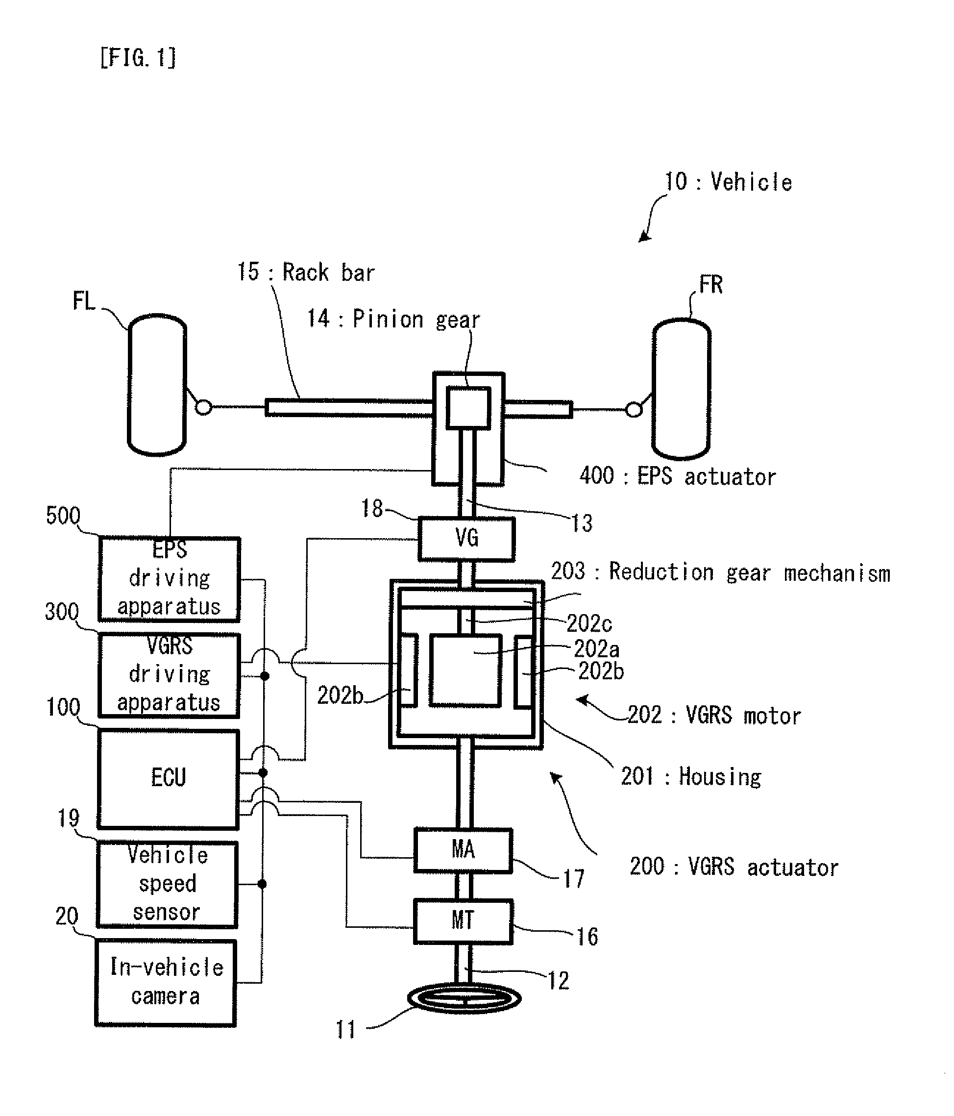
[0090]Firstly, with reference to FIG. 1, the structure of a vehicle 10 in a first embodiment of the present invention will be explained. FIG. 1 is a schematic configuration diagram conceptually showing the structure of the vehicle 10.

[0091]In FIG. 1, the vehicle 10 is provided with a pair of front wheels FL and FR on either sides as steered wheels, and it is constructed to move in a desired direction by steering the front wheels. The vehicle 10 is provided with an ECU 100, a VGRS actuator 200, a VGRS driving apparatus 300, an EPS actuator 400 and an EPS driving apparatus 500.

[0092]The ECU 100 is provided with a CPU (Central Processing Unit), a ROM (Read Only Memory) and a RAM (Random Access Memory), each of which is not illustrated, and it is an electronic control unit capable of controlling all the operations of the vehicle 10. The ECU 100 is one example of the “driving support apparatus of the vehicle” of the present invention. The ECU 100 is constructed to perform each of LKA con...

second embodiment

[0146]Next, as a second embodiment of the present invention, an explanation will be given on LKA control different from that in the first embodiment. Firstly, with reference to FIG. 9, the details of the LKA control in the embodiment will be explained. FIG. 9 is a flowchart showing the LKA control in the second embodiment. Incidentally, in FIG. 9, the overlap points with FIG. 2 will carry the same reference numerals, and the explanation thereof will be omitted as occasion demands. Moreover, the structure of the vehicle in the second embodiment is assumed to be the same as that of the vehicle 10 in the first embodiment.

[0147]In FIG. 9, if calculating the target lateral acceleration GYTG (the step S105), the ECU 100 calculates a LKA front wheel target rudder angle θLKA_FR on the basis of the calculated target lateral acceleration GYTG (step S401). If calculating the LKA front wheel target rudder angle θLKA_FR, the ECU 100 stores the calculated LKA front wheel target rudder angle θLKA_...

third embodiment

[0168]Next, a third embodiment of the present invention will be explained. Firstly, with reference to FIG. 16, the structure of a vehicle 30 in the embodiment will be explained. FIG. 16 is a schematic configuration diagram conceptually showing the basic structure of the vehicle 30. Incidentally, in FIG. 16, the overlap points with FIG. 1 will carry the same reference numerals, and the explanation thereof will be omitted as occasion demands.

[0169]In FIG. 16, the vehicle 30 is different from the vehicle 10 in the first and second embodiment in that the vehicle 30 does not have the VGRS actuator 200 for varying a relation between the steering angle MA of the steering wheel 11 and the rudder angle of the front wheels and its associated equipment, but instead, the vehicle 30 is provided with an ARS 600 for allowing the steering of rear wheels RL and RR. In other words, in the embodiment, the rear wheels function as the “steered wheels” of the present invention. However, the front wheels ...


PUM


Abstract

A vehicle is provided with: an EPS a VGRS actuator as a rudder angle varying device; and an EPS actuator as a steering torque assisting device. In following a target driving route, a LKA target assist torque TLK is outputted from the EPS actuator on the basis of target lateral acceleration GYTG. On the other hand, in order to suppress the steering of a steering wheel by the assist torque, which is against a driver's will, steered wheels are steered by the VGRS actuator, excessively by a LKA correction target angle θLK. At this time, it does not influence a relation between a steering angle and the rotation angle of a lower steering shaft. Thus, the following for the target driving route is realized without reducing the robustness of the vehicle with respect to the driver's steering.

Description

TECHNICAL FIELD[0001]The present invention relates to a driving support apparatus, such as LKA (Lane Keeping Assist), in a vehicle provided with various steering mechanisms, such as EPS (Electronic controlled Power Steering), VGRS (Variable Gear Ratio Steering), ARS (Active Rear Steering), or SBW (Steer By Wire).BACKGROUND ART[0002]As this type of apparatus, there has been suggested an apparatus for enabling lane keeping driving by using an electrically-assisted power steering apparatus and a steering angle varying apparatus (e.g. refer to a patent document 1). According to the steering control apparatus of a vehicle disclosed in the patent document 1 (hereinafter referred to a “conventional technology”), the vehicle can be driven well along a target driving route by controlling the electrically-assisted power steering apparatus to obtain a target rudder angle based on a curvature radius at the time of lane keeping driving and by controlling the deviation of a yaw angle and the late...

Claims


Application Information

Patent Timeline
Patent Type & Authority Applications(United States)
IPC IPC(8): B62D6/00B62D5/04
CPCB62D5/008B62D15/025B62D6/003B62D5/0472B60W10/20B62D5/04B62D6/10
Inventor LIMPIBUNTERNG, THEERAWATKOJO, TAKAHIRO
Owner TOYOTA JIDOSHA KK
Why Eureka
Try Eureka