
Lithographic printing plate support and presensitized plate

a technology of lithographic printing plate and support plate, which is applied in the direction of lithography, foil printing, coating, etc., can solve the problems of not being easy to achieve simple printing, not meeting the requirements of recent years, etc., and achieves excellent on-press developability, excellent scratch resistance, and long press life

Inactive Publication Date: 2011-11-03
FUJIFILM CORP
View PDF2 Cites 18 Cited by
  • Summary
  • Abstract
  • Description
  • Claims
  • Application Information

AI Technical Summary

Benefits of technology

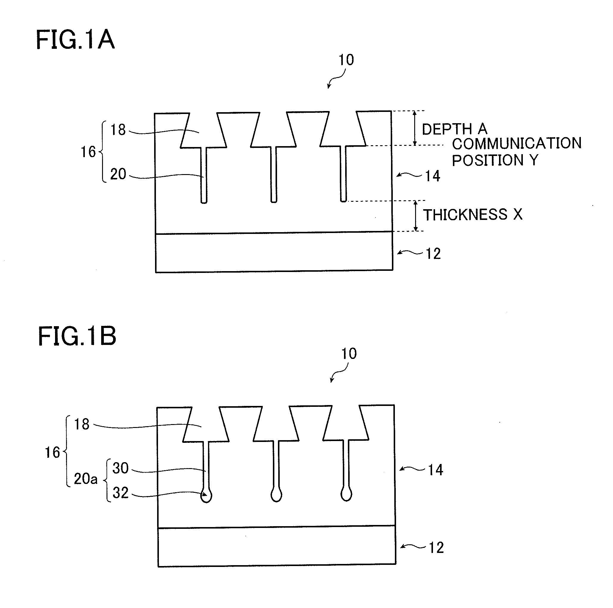
[0049]The surface layer average diameter of the large-diameter portions 18 is not limited as long as it has a specified relation with the average bottom diameter. The surface layer average diameter is preferably at least 10 nm, more preferably from 12 to 40 nm and even more preferably from 14 to 30 nm in terms of more excellent effects of the invention.
[0050]The surface layer average diameter of the large-diameter portions 18 is determined by observing the surface of the anodized film 14 by FE-TEM at a magnification of 500,000×, measuring the diameter of 60 (N=60) micropores (large-diameter portions) and calculating the average of the measurements.
[0051]The average bottom diameter of the large-diameter portions 18 is determined by observing the cross-sectional surface at the communication position Y of the anodized film 14 by FE-TEM at a magnification of 500,000×, measuring the diameter of 60 (N=60) micropores (large-diameter portions) and calculating the average of the measurements. Any known method may be applied to make the measurement on the cross-sectional surface of the anodized film. For example, the anodized film is cut by focused ion beam (FIB) milling to prepare a thin film with a thickness of about 50 nm, which is used to make the measurement on the cross-sectional surface of the anodized film 14.
[0052]The equivalent circle diameter is used if the aperture and bottom of the large-diameter portion 18 are not circular. The “equivalent circle diameter” refers to a diameter of a circle assuming that the shape of an aperture (bottom) is the circle having the same projected area as that of the aperture (bottom).
[0053]The bottom of each large-diameter portion 18 is at a depth of 5 to 60 nm from the surface of the anodized film (hereinafter this depth is also referred to as “depth A”). In other words, each large-diameter portion 18 is a pore which extends from the surface of the anodized film in the depth direction (thickness direction of the anodized film) to a depth of 5 to 60 nm. The depth is preferably from 10 nm to 50 nm from the viewpoint that the lithographic printing plate obtained using the lithographic printing plate support has a longer press life and more excellent deinking ability in continued printing and after suspended printing and the presensitized plate obtained using the support has more excellent on-press developability.
[0054]At a depth of less than 5 nm, a sufficient anchor effect is not obtained, nor is the press life of the lithographic printing plate improved, and the presensitized plate has poor on-press developability. At a depth in excess of 60 nm, the lithographic printing plate has poor deinking ability after suspended printing and the presensitized plate has poor on-press developability.

Problems solved by technology

The inventors of the invention have made studies on various properties of the lithographic printing plates and the presensitized plates obtained using lithographic printing plate supports which are obtained by performing anodizing treatment in two steps as specifically described in the five patent documents mentioned above, and as a result found that these properties do not meet the levels required in recent years.
In other words, it was not necessarily easy to achieve simple printing while keeping high image quality.

Method used


Image

  • Lithographic printing plate support and presensitized plate
  • Lithographic printing plate support and presensitized plate
  • Lithographic printing plate support and presensitized plate

Examples


embodiment

Preferred Embodiment

[0174]On the other hand, in the present invention, the lithographic printing plate support is preferably obtained by subjecting the aluminum plate to the respective treatments described in Embodiment A in the order shown below. Rinsing with water is desirably performed between the respective treatments. However, in cases where a solution of the same composition is used in the two consecutive steps (treatments), rinsing with water may be omitted.

embodiment a

[0175](1) Mechanical graining treatment;

[0176](2) Chemical etching treatment in an aqueous alkali solution (first alkali etching treatment);

[0177](3) Chemical etching treatment in an aqueous acid solution (first desmutting treatment);

[0178](4) Electrochemical graining treatment in a nitric acid-based aqueous solution (first electrochemical graining treatment);

[0179](5) Chemical etching treatment in an aqueous alkali solution (second alkali etching treatment);

[0180](6) Chemical etching treatment in an aqueous acid solution (second desmutting treatment);

[0181](7) Electrochemical graining treatment in a hydrochloric acid-based aqueous solution (second electrochemical graining treatment);

[0182](8) Chemical etching treatment in an aqueous alkali solution (third alkali etching treatment);

[0183](9) Chemical etching treatment in an aqueous acid solution

[0184](third desmutting treatment);

[0185](10) Anodizing treatments (first to third anodizing treatments);

[0186](11) Hydrophilizing treatment...

synthesis example 1

Synthesis of Polymer No. 1

[0402]Into a nitrogen-purged three-necked flask were introduced 10.0 parts of M-11 (shown below), 75.0 parts of a terminal-methacryloylized polymethyl methacrylate [number-average molecular weight: 6,000: AA-6 available from Toagosei Co., Ltd.; abbreviated as MM-1], 15.0 parts of methacrylic acid and 334.0 parts of 1-methoxy-2-propanol. The mixture was stirred in an agitator (Three-One Motor available from Shinto Scientific Co., Ltd.) and heated to 90° C. as nitrogen was flowed through the flask.

[0403]To the mixture was added 0.5 part of 2,2-azobis(2,4-dimethylvaleronitrile) (V-65 available from Wako Pure Chemical Industries, Ltd.) and the mixture was heated with stirring at 90° C. for 2 hours. After 2 hours, 0.5 part of V-65 was further added. After heating with stirring for 3 hours, a 30% solution of graft polymer compound (Polymer No. 1) which had a MM-1-derived side chain on the main chain derived from methyl methacrylate and methacrylic acid was obtain...


PUM

PropertyMeasurementUnit
diameteraaaaaaaaaa
diameteraaaaaaaaaa
diameteraaaaaaaaaa

Abstract

The lithographic printing plate support includes an aluminum plate and an anodized film formed on the aluminum plate and micropores extend in the anodized film in a depth direction from its surface opposite from the aluminum plate. Each of the micropores includes a large-diameter portion having a predetermined shape and a small-diameter portion having a predetermined shape. The lithographic printing plate support has excellent scratch resistance and is capable of obtaining a presensitized plate which exhibits excellent on-press developability and enables a lithographic printing plate formed therefrom to have a long press life, and excellent deinking ability in continued printing and after suspended printing.

Description

TECHNICAL FIELD[0001]The present invention relates to a lithographic printing plate support and a presensitized plate.BACKGROUND ART[0002]Lithographic printing is a printing process that makes use of the inherent immiscibility of water and oil. Lithographic printing plates used in lithographic printing have formed on a surface thereof regions which are receptive to water and repel oil-based inks (referred to below as “non-image areas”) and regions which repel water and are receptive to oil-based inks (referred to below as “image areas”).[0003]The aluminum support employed in a lithographic printing plate (referred to below simply as a “lithographic printing plate support”) is used in such a way as to carry non-image areas on its surface. It must therefore have a number of conflicting properties, including, on the one hand, an excellent hydrophilicity and water retention and, on the other hand, an excellent adhesion to the image recording layer that is provided thereon. If the hydrop...

Claims


Application Information

Patent Timeline
Patent Type & Authority Applications(United States)
IPC IPC(8): B41N1/00B41N3/00
CPCB41C1/1008B41N1/083B41N3/034C25D11/08C25D11/12B41C1/1016C25F3/04B41C2201/04B41C2201/14B41C2210/04B41C2210/08B41C2210/22B41C2210/24B41C2201/02
Inventor TAGAWA, YOSHIHARUSAWADA, HIROKAZUNISHINO, ATSUOKUROKAWA, SHINYAMIYAGAWA, YUYA
Owner FUJIFILM CORP
Learn More