Apparatuses, Systems and Methods For Efficient Solubilization Of Carbon Dioxide In Water Using High Energy Impact

a technology of carbon dioxide and water, applied in the direction of dissolving, separation processes, applications, etc., can solve the problems of weak carbonation of water, high energy impact of water pump, poor solubility of carbon dioxide in water, etc., and achieve the effect of increasing the kinetic energy of the system

Active Publication Date: 2011-11-03
APIQE HLDG
View PDF13 Cites 35 Cited by
  • Summary
  • Abstract
  • Description
  • Claims
  • Application Information

AI Technical Summary

Benefits of technology

[0007]In accordance with another exemplary embodiment of present disclosure an apparatus is disclosed that can be placed in a water line path to create carbonated water for dispensing. Advantageously, the apparatus accepts carbon dioxide and water through an inlet path. From there the flow of carbon dioxide and water are passed through one or more dispersion elements arranged within the conduit to create a dispersed flow. The dispersed flow then passes through a passive accelerator within the conduit, thereby greatly increasing the kinetic energy of the system. The accelerated flow is directed to collide with a rigid impact surface immediately downstream of the passive accelerator. This collision creates sufficient pressure to solubilize the carbon dioxide into the water. A retention network is provided at the output of the apparatus to collect and regulate the flow of carbonated water.

Problems solved by technology

Most commercialized devices for carbonating water use carbon dioxide sprayed into a water container: the result obtained with this process is very poor and the carbonation of water is weak and does not last too long.
Due to the high pressures resident in the saturator tank, typically around 70 psi, a relatively expensive high-pressure water pump is required to inject water into the tank.
Accordingly, the saturator is typically large enough to hold a ready supply of carbonated water for dispensing and does not create new carbonated water instantaneously on demand.
These typical carbonization devices take up a relatively large amount of space and require expensive and complicated electronic and hydraulic control systems.
Due to this complex structure, these devices are noisy, use significant amounts of energy, and require frequent maintenance.

Method used


Image

  • Apparatuses, Systems and Methods For Efficient Solubilization Of Carbon Dioxide In Water Using High Energy Impact
  • Apparatuses, Systems and Methods For Efficient Solubilization Of Carbon Dioxide In Water Using High Energy Impact
  • Apparatuses, Systems and Methods For Efficient Solubilization Of Carbon Dioxide In Water Using High Energy Impact

Examples


Embodiment Construction

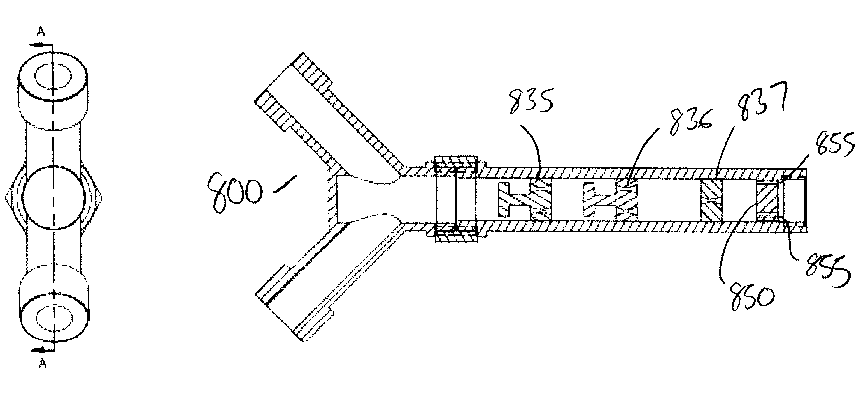
[0020]Apparatuses, systems and methods are disclosed herein for the quick and efficient solubilization of carbon dioxide in water. In particular, carbonated water is created through the instantaneous transformation of kinetic energy into a localized pressure wave to create a region with an energy density sufficient to solubilize carbon dioxide into water. This can be achieved through the use of an apparatus that sits in-line with the water supply to create a continuous flow of carbonated water.

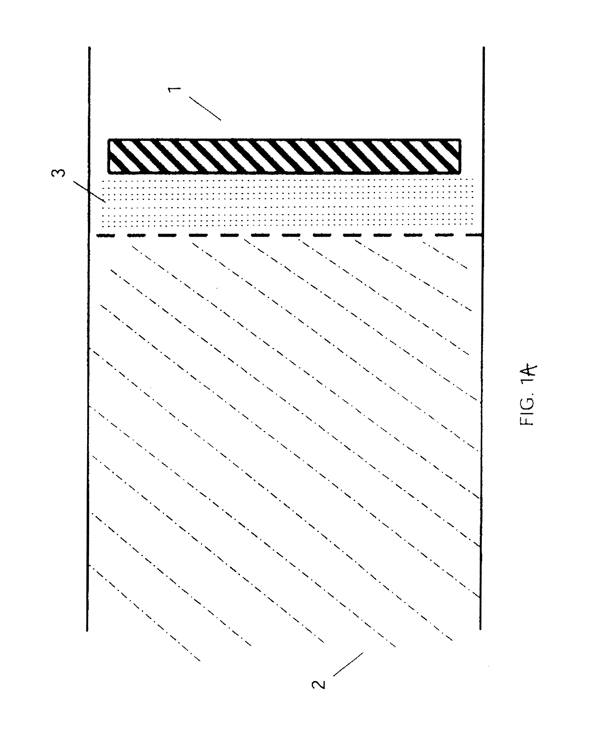
[0021]One particularly advantageous aspect of the disclosed method is the solubilization of carbon dioxide in water through the collision of a carbon dioxide / water stream with a rigid surface. FIG. 1A shows conceptual diagram of the interactions occurring in an exemplary collision in accordance with the present invention.

[0022]As shown in FIG. 1A, a carbon dioxide / water stream 2 is directed at a rigid surface, such as wall 1. Upon collision with the wall the momentum of the stream 2 is suddenl...


PUM

PropertyMeasurementUnit
pressureaaaaaaaaaa
pressureaaaaaaaaaa
pressureaaaaaaaaaa

Abstract

A method for the efficient solubilization of carbon dioxide in water through the use of high energy impacts is disclosed. The method can optionally includes mixing the carbon dioxide and water to form an annular dispersed flow, accelerating the carbon dioxide and water prior to the collision; providing a retention network to collect the carbonated water flow. Also disclosed are systems and apparatuses for practicing the disclosed methods.

Description

FIELD OF THE INVENTION[0001]The present disclosure relates to apparatuses, systems and methods for solubilizing gases into liquids and, in particular, creating carbonated beverages for human consumption.BACKGROUND OF THE INVENTION[0002]Water and carbon dioxide are generally immiscible under normal environmental conditions, i.e., room temperature and atmospheric pressure. Apparatuses and methods are known for producing carbonated water by creating conditions under which carbon dioxide will become water-soluble. Generally, carbon dioxide becomes more soluble in water as pressures increase and temperatures decrease.[0003]Most commercialized devices for carbonating water use carbon dioxide sprayed into a water container: the result obtained with this process is very poor and the carbonation of water is weak and does not last too long. Devices for producing and dispensing carbonated beverages in water dispensing units, instead, typically employ a carbonating tank, called a saturator, and...

Claims


Application Information

Patent Timeline
Patent Type & Authority Applications(United States)
IPC IPC(8): A23L2/54B01F3/04
CPCA23L2/54A23V2002/00B01F3/04503B01F3/04787B01F5/0615B01F5/0641B01F3/04985B01F11/0208B01F2215/045B01F2215/0468B01F5/0688A23V2250/11B01F23/2323B01F23/236B01F25/43141B01F25/4321B01F25/4521B01F31/81Y02C20/40B01F21/00B01F23/20B01F25/20B01F25/30B01F25/40B01F23/2362B01F23/29B01F25/431B01F2101/14A47J31/00
Inventor FANTAPPIE, GIANCARLO
Owner APIQE HLDG
Why Eureka
Try Eureka