Automotive controlling apparatus-integrated dynamoelectric machine

a technology of dynamoelectric machine and controlling apparatus, which is applied in the direction of cooling/ventilation arrangement, magnetic circuit rotating parts, and shape/form/construction of magnetic circuits, etc., can solve the problem that the controlling apparatus is easily damaged by external mechanical shocks, and achieve the effect of damage to the controlling apparatus

Active Publication Date: 2011-11-10
MITSUBISHI ELECTRIC CORP
View PDF19 Cites 32 Cited by
  • Summary
  • Abstract
  • Description
  • Claims
  • Application Information

AI Technical Summary

Benefits of technology

According to the present invention, because the controlling apparatus is disposed inside the metal rear bracket, external mechanical shocks do not act directly on the controlling apparatus, and airborne objects will not collide into the controlling apparatus. Thus, damage to the controlling apparatus that results from external mechanical shocks and collisions with airborne objects, etc., can be suppressed.

Problems solved by technology

In conventional controlling apparatus-integrated dynamoelectric machines, because the controlling apparatus is disposed axially outside the rear bracket of the dynamoelectric machine, one problem has been that the controlling apparatus is easily damaged by external mechanical shocks, or by collisions with airborne objects, etc.

Method used


Image

  • Automotive controlling apparatus-integrated dynamoelectric machine
  • Automotive controlling apparatus-integrated dynamoelectric machine
  • Automotive controlling apparatus-integrated dynamoelectric machine

Examples


embodiment 1

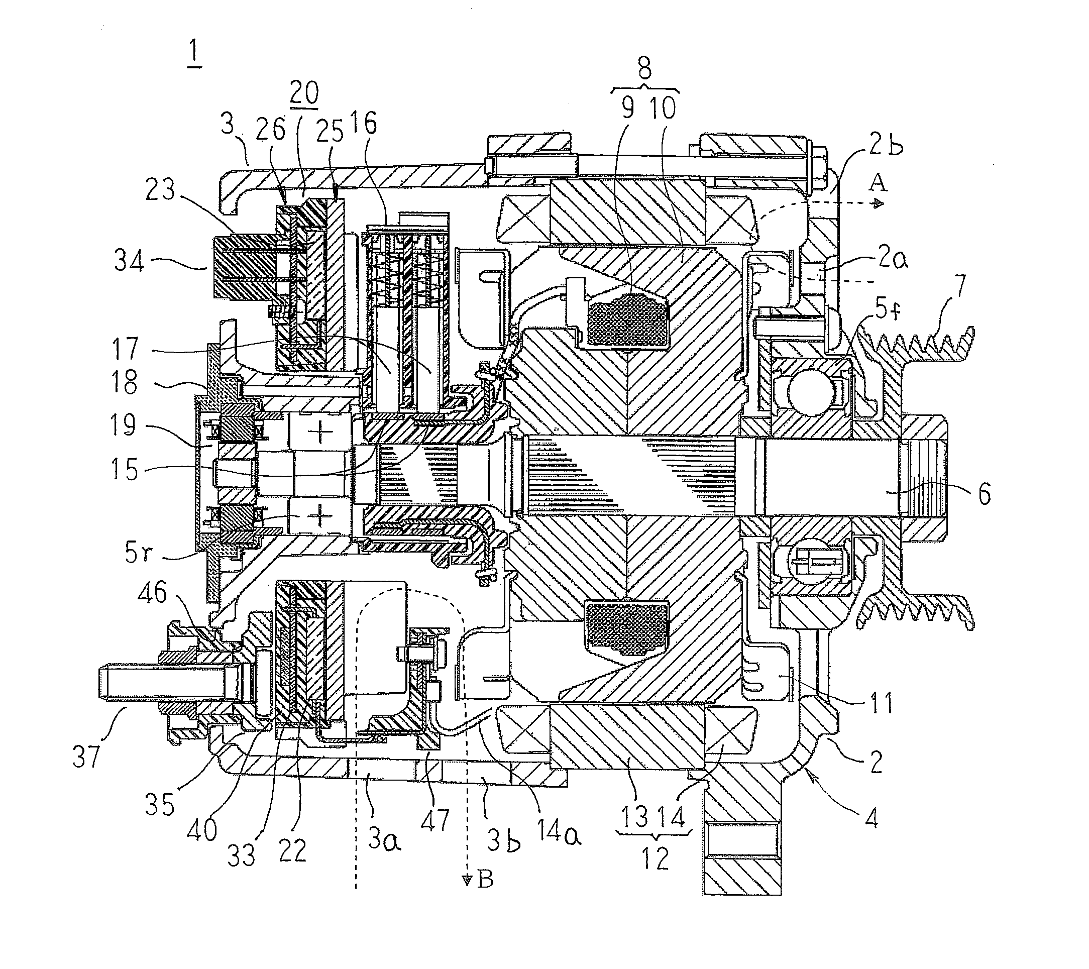
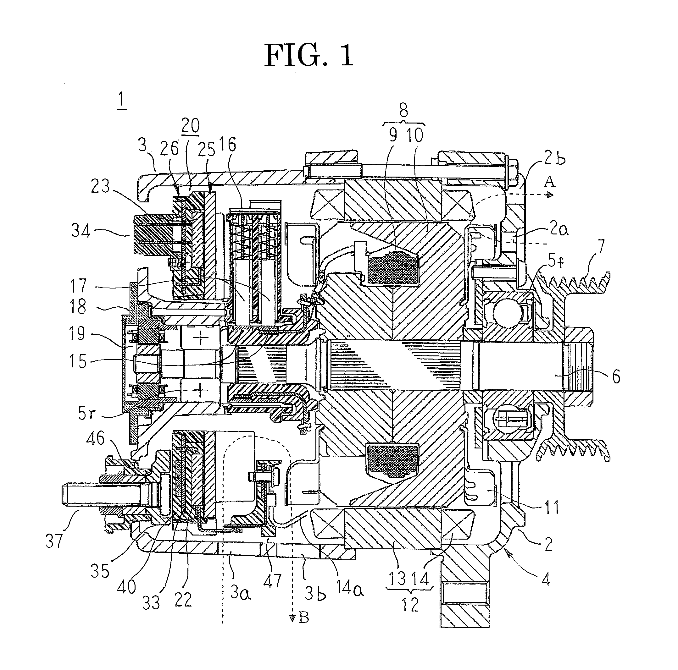
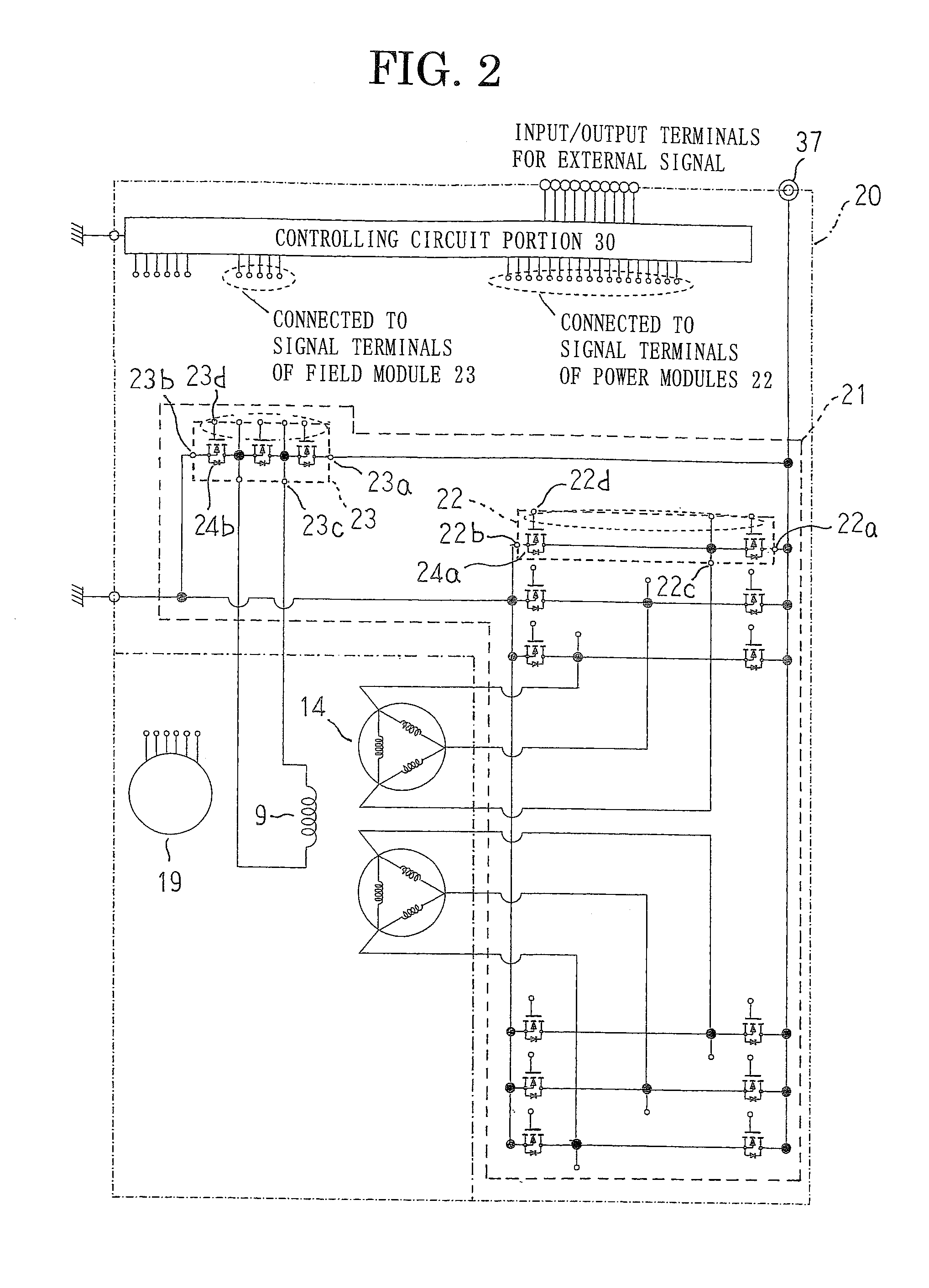
FIG. 1 is a longitudinal cross section that shows an automotive controlling apparatus-integrated dynamoelectric machine according to Embodiment 1 of the present invention, FIG. 2 is an electrical circuit diagram of the automotive controlling apparatus-integrated dynamoelectric machine according to Embodiment 1 of the present invention, FIG. 3 is a view from a rear end of a cross section in which a state of a controlling apparatus before mounting a controlling circuit board is sectioned in a plane that is perpendicular to an axial direction in the automotive controlling apparatus-integrated dynamoelectric machine according to Embodiment 1 of the present invention, FIG. 4 is a view from a rear end of a state of the controlling apparatus before mounting a bus bar in the automotive controlling apparatus-integrated dynamoelectric machine according to Embodiment 1 of the present invention, FIG. 5 is a view from a rear end of the controlling apparatus in the automotive controlling apparatu...

embodiment 2

FIG. 11 is a partial cross section that shows a vicinity of a field module of a controlling apparatus in an automotive controlling apparatus-integrated dynamoelectric machine according to Embodiment 2 of the present invention, and FIG. 12 is a partial cross section that shows a vicinity of a power module of the controlling apparatus in the automotive controlling apparatus-integrated dynamoelectric machine according to Embodiment 2 of the present invention.

In FIGS. 11 and 12, a resin cover 50 is fixed to an outer peripheral partitioning wall 26b and an inner peripheral partitioning wall 26c of a resin case 26 using an adhesive 51 and a screw (not shown), and covers a housing space 49 that houses power modules 22, a field module 23, and a controlling circuit board 33. A packing 52 is interposed between a connector 34 and the cover 50 to ensure water proofing. An air-permeable filter 53 that has dustproofing, waterproofing, and water repelling functions is mounted to the cover 50. The ...


PUM


Abstract

A controlling apparatus-integrated dynamoelectric machine Includes: a metal housing that includes a front bracket and a rear bracket; a rotor that is rotatably disposed inside the housing by being fixed to a shaft that is rotatably supported by the front bracket and the rear bracket; a stator that includes: a cylindrical stator core that is disposed so as to be held between the front bracket and the rear bracket so as to surround the rotor; and a stator winding that is mounted to the stator core; and a controlling apparatus that includes: a direct-current alternating-current power interconverting circuit portion that passes electric current to the stator winding; and a controlling circuit portion that controls the direct-current alternating-current power interconverting circuit portion, the controlling apparatus being disposed inside the rear bracket.

Description

BACKGROUND OF THE INVENTION1. Field of the InventionThe present invention relates to an automotive controlling apparatus-integrated dynamoelectric machine that includes a controlling apparatus that is constituted by a direct-current alternating-current power interconverting circuit and a controlling circuit that controls the direct-current alternating-current power interconverting circuit, and that has a generating function and an electric motor function.2. Description of the Related ArtConventional controlling apparatus-integrated dynamoelectric machines include: a dynamoelectric machine that has a generating function and an electric motor function; and a controlling apparatus that includes a power circuit portion, a controlling circuit board, and a field current controlling circuit portion, the power circuit portion and the field current controlling circuit portion being housed inside a housing space that is configured by a rear bracket of the dynamoelectric machine and a resin co...

Claims


Application Information

Patent Timeline
Patent Type & Authority Applications(United States)
IPC IPC(8): H02K9/06H02K9/22H02K11/04
CPCH02K19/365H02K11/046H02K5/225H02K11/05
Inventor ISODA, HITOSHIFUJITA, MASAHIKO
Owner MITSUBISHI ELECTRIC CORP
Why Eureka
Try Eureka