Valve control device

a control device and valve technology, applied in the direction of electric controllers, dynamo-electric converter control, dynamo-electric gear control, etc., can solve the problem of presenting an oscillatory response defect, achieve the effect of generating motor torque, preventing a collision of valves, and reducing the speed by motor torqu

Active Publication Date: 2011-11-10
MITSUBISHI ELECTRIC CORP
View PDF2 Cites 29 Cited by
  • Summary
  • Abstract
  • Description
  • Claims
  • Application Information

AI Technical Summary

Benefits of technology

[0015]According to the valve control device according to the present invention, the current control system can be configured to have the virtual current feedback using a sensor having a coarse electrical angle resolution. Then, the torque is directly controlled by the current control system, and the response of the motor can thus be accelerated. Moreover, wide-band torque control by this current control system can be used to effectively generate a motor torque opposing to a return toque particularly at a low speed motor rotation, thereby decreasing the speed by the motor torque even if the return torque is generated in the accelerating direction, resulting in prevention of a collision of the valve to the mechanical end. Further, the configuration does not require a current sensor, and the cost of the control system can thus be reduced.

Problems solved by technology

On the other hand, in the voltage control method, the influence of the current lag due to the inductance component of the motor windings with respect to the voltage command cannot be neglected and the torque tracking characteristic is deteriorated compared to the current control method, resulting in a defect of presenting an oscillatory response.

Method used


Image

  • Valve control device
  • Valve control device
  • Valve control device

Examples


first embodiment

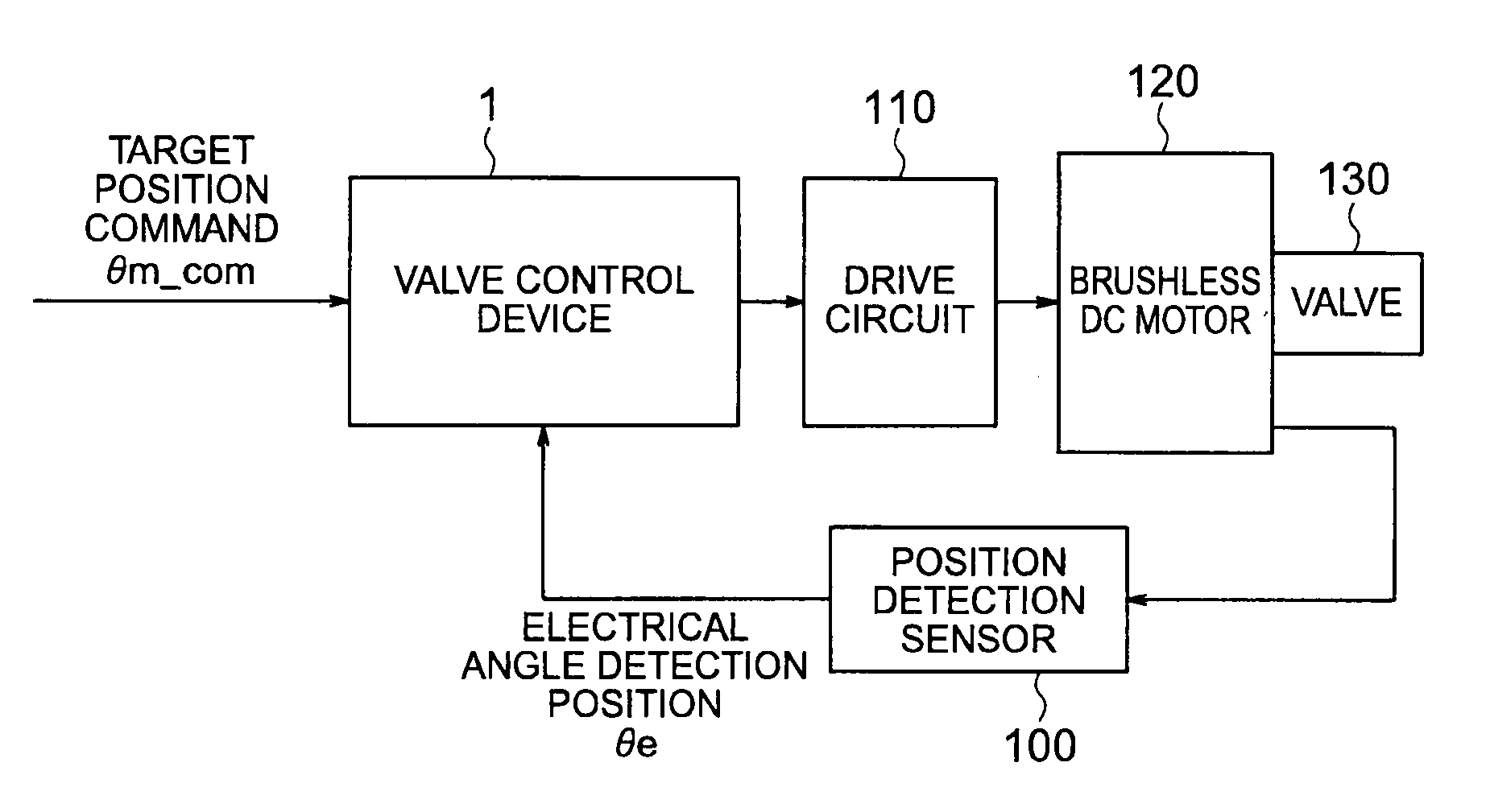
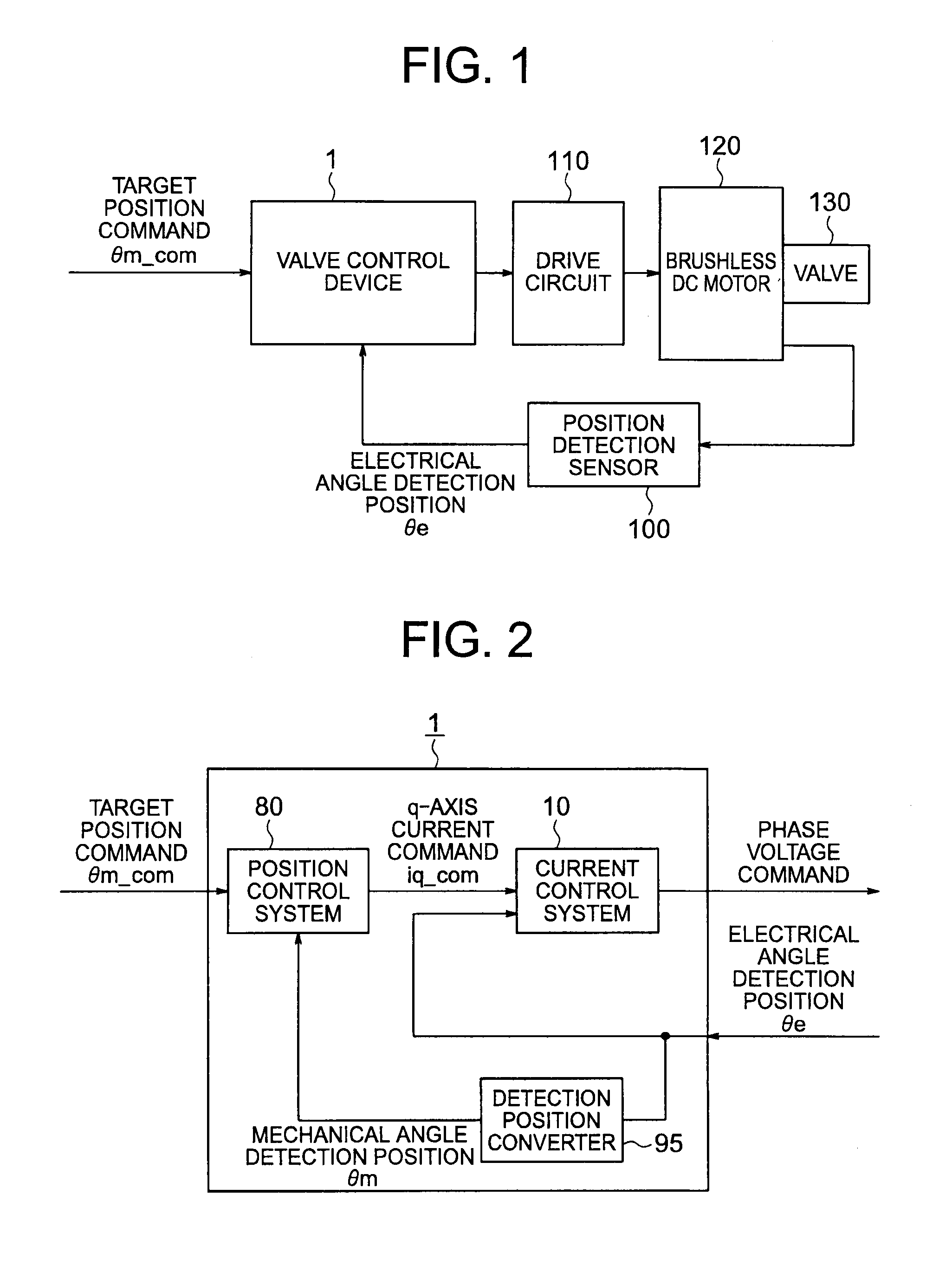
[0033]A description is given of the valve control device according to a first embodiment of the present invention referring to FIGS. 1 to 14. FIG. 1 is a block diagram illustrating an overall configuration of a control system including the valve control device according to the first embodiment of the present invention. It should be noted that like numerals denote like or corresponding components throughout the drawings hereinafter.

[0034]In FIG. 1, the control system includes a valve control device 1, a position detection sensor 100, a drive circuit 110, a brushless DC motor 120, and a valve 130.

[0035]In FIG. 1, an actuator for driving the valve 130 is the brushless DC motor 120. Moreover, the position detection sensor 100 of the pulse output type such as a Hall IC is provided to the brushless DC motor 120. The resolution of the position detection sensor 100 corresponds to six steps per period of the electrical angle, namely the electrical angle resolution is 60 deg.

[0036]A spring (n...

second embodiment

[0081]A description is now given of a valve control device according to a second embodiment of the present invention referring to FIG. 15. FIG. 15 is a block diagram illustrating a configuration of a current control system of the valve control device according to the second embodiment of the present invention.

[0082]In FIG. 15 A, a current control system 10A of the valve control device 1 according to the second embodiment of the present invention includes a phase corrector 90A for providing an optimal phase correction amount in accordance with the motor angular velocity. The current control system 10A is different from the current control system 10 of the valve control device 1 according to the first embodiment, in which the base corrector 90 sets the phase lag amount dθe as the fixed value determined by the maximum motor angular velocity. Thus, while the phase correction amount (equal to dθe) is constant according to the first embodiment, the phase correction amount changes in accor...

third embodiment

[0087]A description is now given of a valve control device according to a third embodiment of the present invention referring to FIG. 16. FIG. 16 is a block diagram illustrating a configuration of a current control system of the valve control device according to the third embodiment of the present invention.

[0088]The valve control device 1 according to the third embodiment of the present invention has the following configuration. In the current control system 10 of the valve control device 1 according to the above-mentioned first embodiment, the estimated current for each of the phases is calculated using the actual phase voltage in place of the phase voltage command.

[0089]When the actual phase voltage is used, an actual U-phase voltage and an actual V-phase voltage are respectively smoothed by filters 91 and 92 in order to attenuate noise in synchronism with a PWM carrier frequency, thereby using the Actual U-phase voltage and the Actual V-phase voltage for the current estimation. ...


PUM


Abstract

In opening / closing control for the valve mechanism to which the return torque is applied in an opening direction or a closing direction of the valve, provided are a position control system for outputting a q-axis current command based on a position deviation between a target position command directed to the brushless DC motor and the coarse present position of the motor obtained by using the position detection sensor of a pulse output type, and a current control system in which a virtual current feedback is built for outputting a phase voltage command without a current sensor based on the q-axis current command and the coarse present position of the motor obtained by using the position detection sensor of the pulse output type.

Description

TECHNICAL FIELD[0001]The present invention relates to a valve control device for a valve that is used, for example, for electronic throttling and exhaust gas recirculation, and is driven by a brushless DC motor.BACKGROUND ART[0002]For speed control and position control for a system driven by a motor, there are a “voltage control method” of generating a voltage command directed to the motor based on a deviation between a command and an actual value, and a “current control method” of feeding back an actual current flowing through a winding of the motor so as to control the actual current to coincide with a current command.[0003]The latter current control method applies the control forcedly overcoming the inductance component of the motor windings, and a current lag due to the inductance component in a control bandwidth of a current control system can thus be neglected, thereby providing stable torque control from a low speed range to a high speed range of the motor. On the other hand,...

Claims


Application Information

Patent Timeline
Patent Type & Authority Applications(United States)
IPC IPC(8): G05B11/01F02D9/02F02D11/10H02P21/00F02M26/00F02M26/48F02M26/54H02P6/06H02P6/08H02P6/16H02P6/28H02P21/13H02P21/22H02P23/30H02P25/022H02P25/026H02P27/04H02P27/08
CPCF02D41/1497F02D41/20F02D2041/2058F02D2200/0404H02P6/085H02P6/08H02P21/06H02P21/14F02D2250/14H02P6/16H02P23/00H02P6/10
Inventor IMAMURA, NAOKIIEZAWA, MASAHIROKAWAMURA, SATOSHIONISHI, YOSHITAKA
Owner MITSUBISHI ELECTRIC CORP
Why Eureka
Try Eureka