

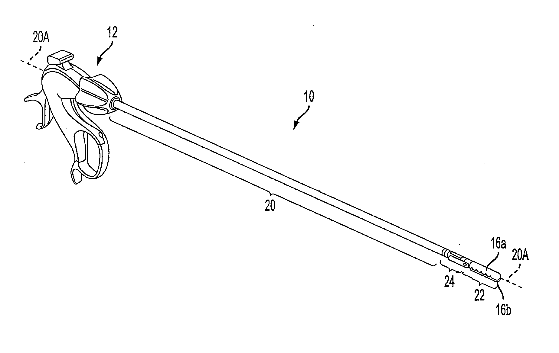
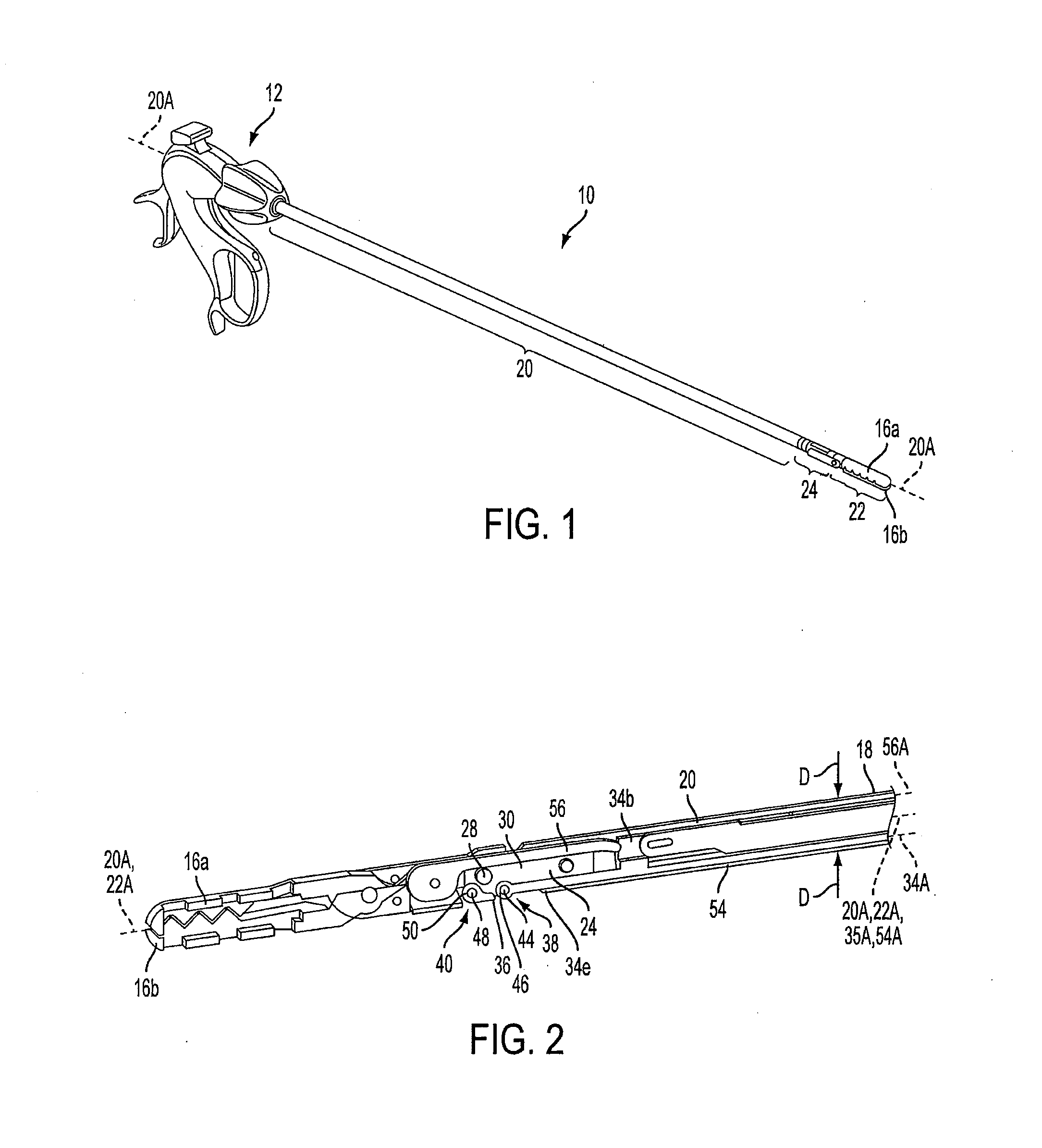
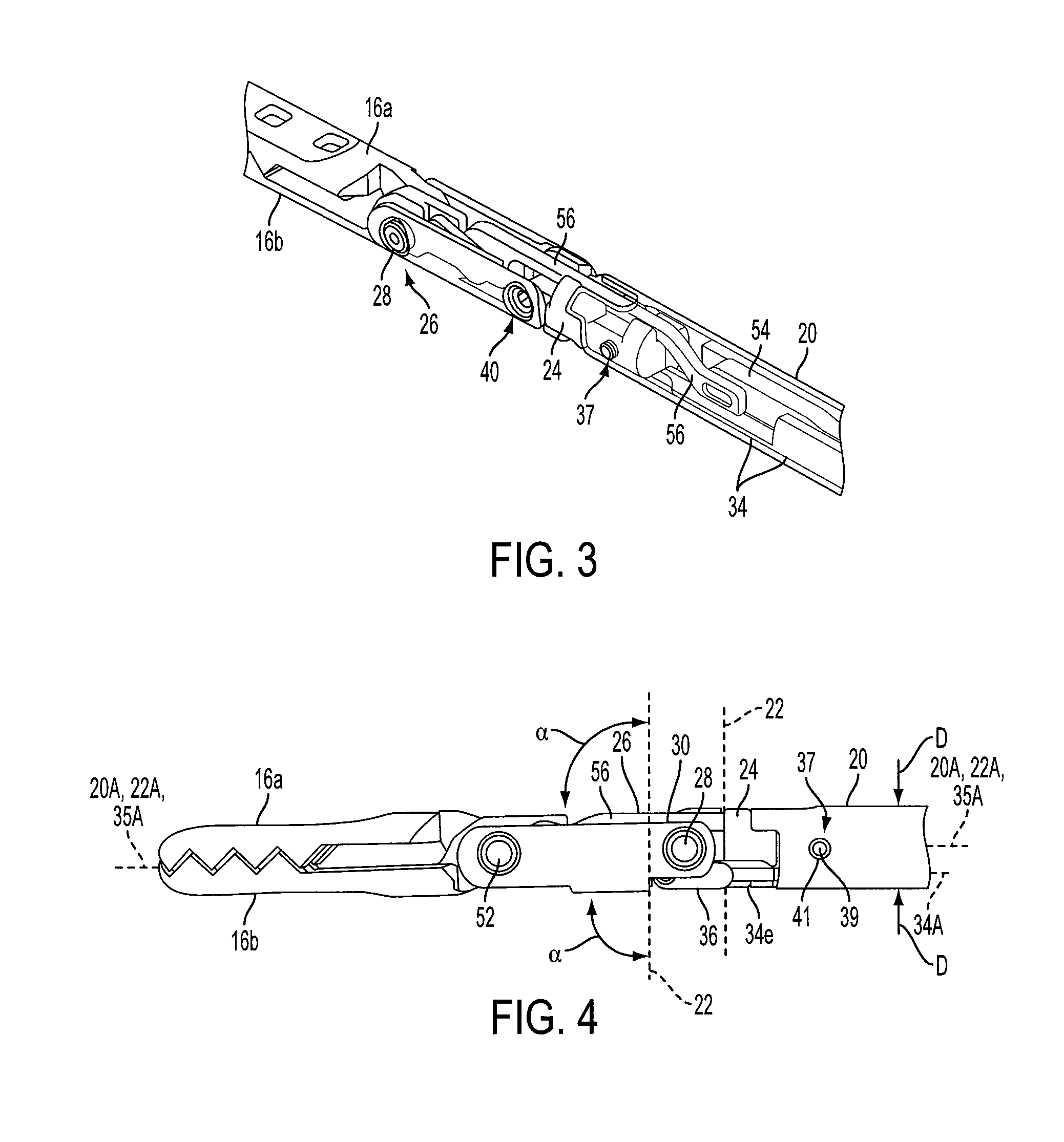
Laparoscopic devices with articulating end effectors
a technology of end effectors and laparoscopic devices, which is applied in the field of laparoscopic devices, can solve the problems of difficult or impossible to see difficult or impossible to visualize the tips of the instruments, and difficult visualization and triangulation
- Summary
- Abstract
- Description
- Claims
- Application Information
AI Technical Summary
Benefits of technology
Problems solved by technology
Method used
Image

Examples
Embodiment Construction
[0052]Certain exemplary embodiments will now be described to provide an overall understanding of the principles of the structure, function, manufacture, and use of the devices and methods disclosed herein. One or more examples of these embodiments are illustrated in the accompanying drawings. Those skilled in the art will understand that the devices and methods specifically described herein and illustrated in the accompanying drawings are non-limiting exemplary embodiments and that the scope of the present invention is defined solely by the claims. The features illustrated or described in connection with one exemplary embodiment may be combined with the features of other embodiments. Such modifications and variations are intended to be included within the scope of the present invention.
[0053]Various exemplary devices and methods are provided for performing minimally invasive surgical procedures. In general, the devices and methods allow a working end of a surgical instrument to arti...
PUM
 Abstract
Description
Claims
Application Information