Radiation Beam Analyzer And Method

a radiation beam and analyzer technology, applied in the field of radiation beam analyzer and method, can solve the problems of not using devices, not yielding an appropriate three-dimensional assessment of the combination of scattering, and providing a planar scan of the beam, so as to achieve accurate positioning of the radiation detector, and accurate positioning of the linear accelerator

Active Publication Date: 2011-11-17
NAVARRO DANIEL
View PDF7 Cites 19 Cited by
  • Summary
  • Abstract
  • Description
  • Claims
  • Application Information

AI Technical Summary

Benefits of technology

[0029]It is a still further objective of the present invention to provide a mechanism to rotate a tank of water to enable accurate positioning of a linear accelerator.
[0030]It is a still further objective of the present invention to provide a mechanism to rotate

Problems solved by technology

While these devices employ a water phantom, they are limited to moving the signal detector along the single axis and can only provide a planar scan of the beam.
These devices do not use a water phantom and are additionally limited in that all of the ionization detectors are in one plane.
This does not yield an appropriate three-dimensional assessment of the combination of scattering and direct radiation which would normally impinge the human body undergoing radiation treatment.
Thus, accurate dosimetry in a real-life scenario could not be readily ascerta

Method used


Image

  • Radiation Beam Analyzer And Method
  • Radiation Beam Analyzer And Method
  • Radiation Beam Analyzer And Method

Examples


first embodiment

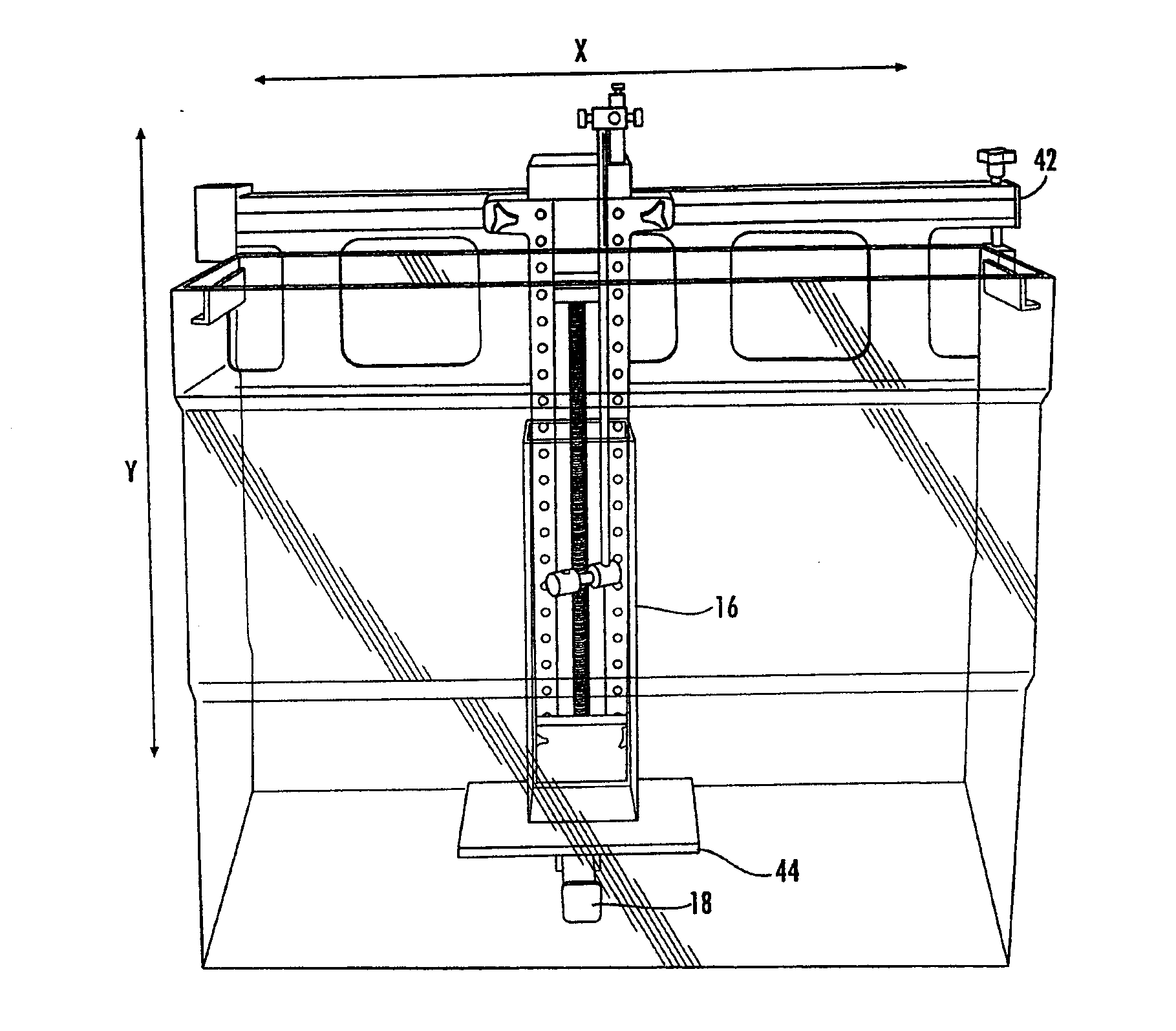
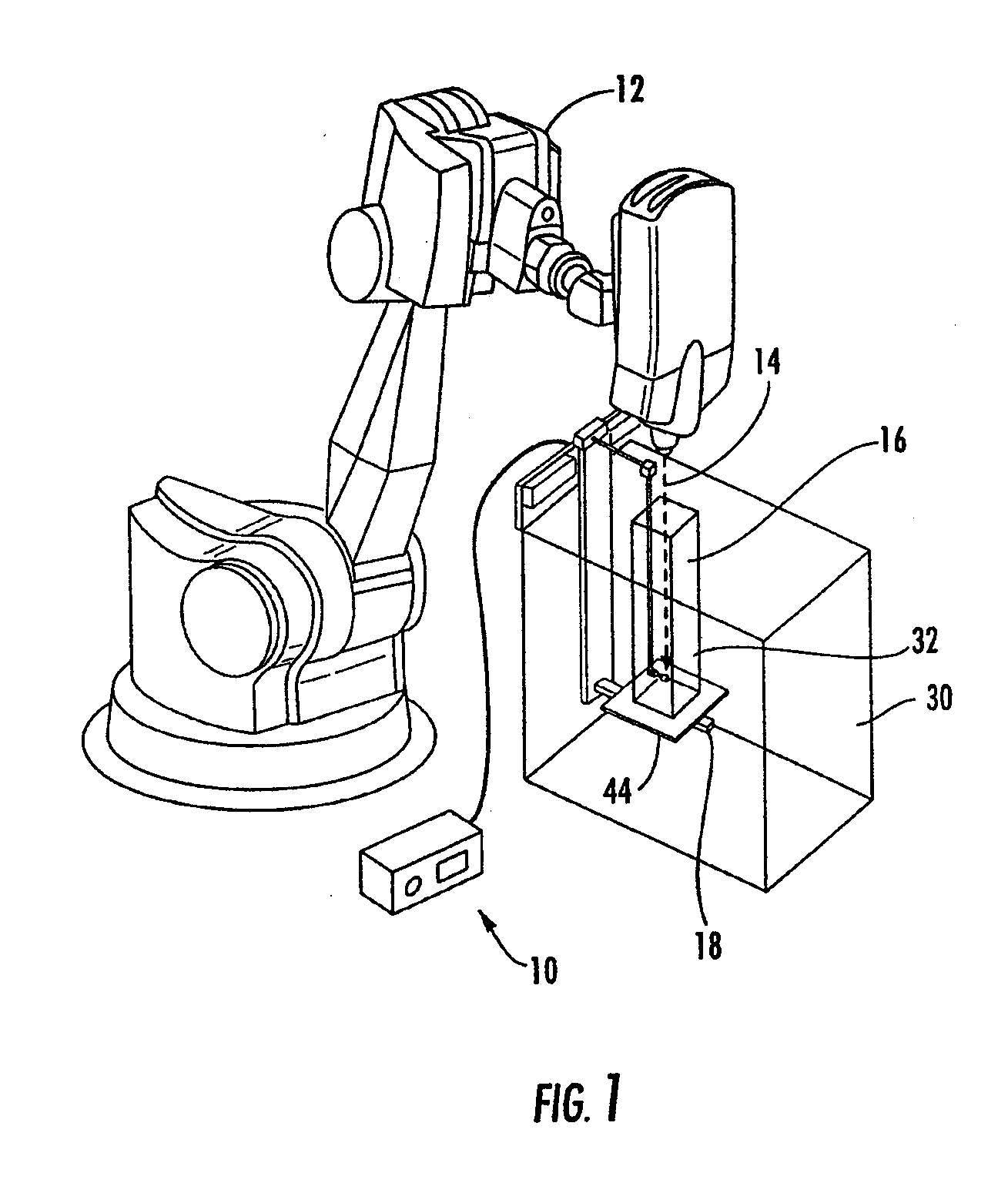
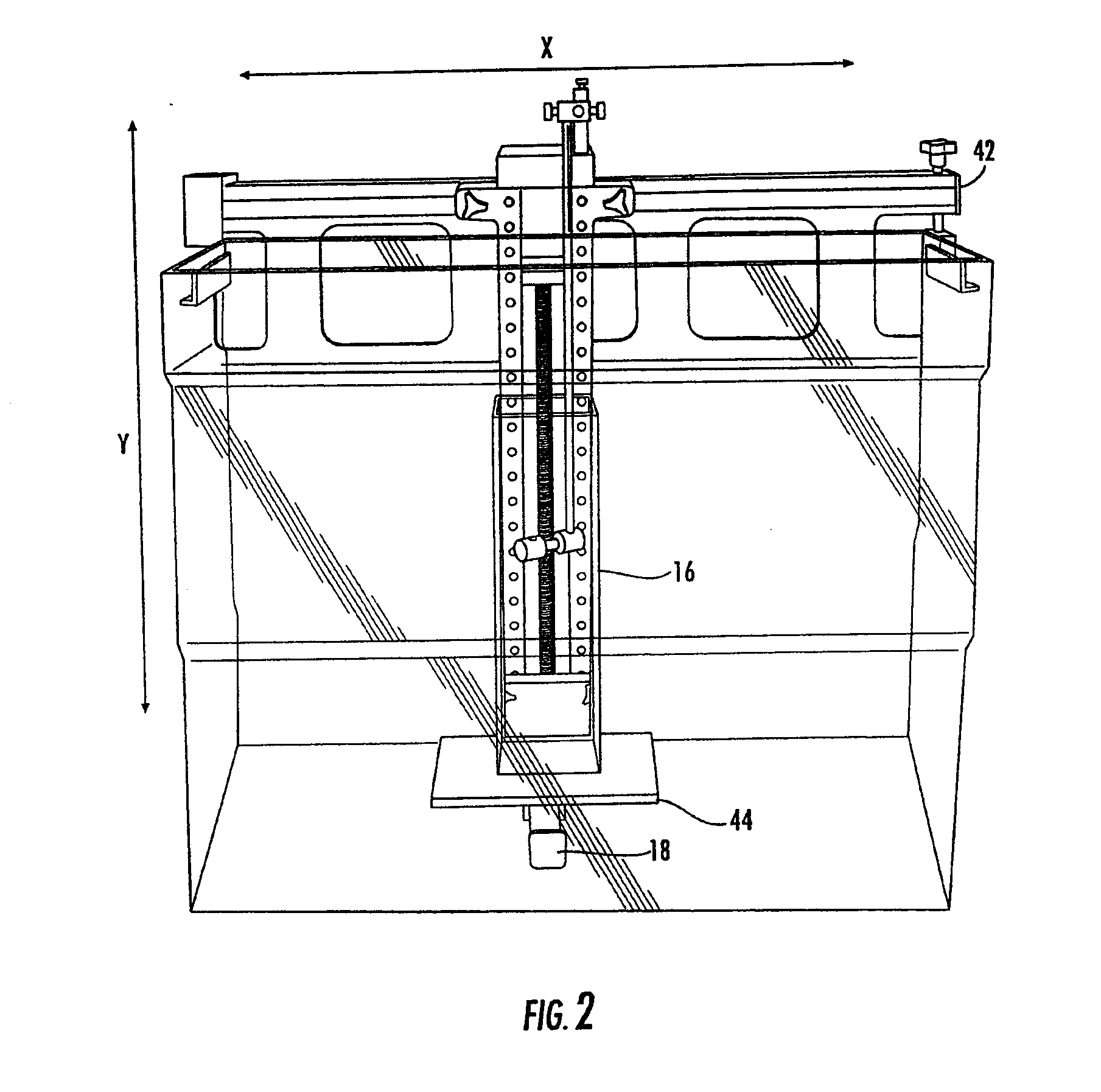
[0059]Referring to FIGS. 1-6, the invention including a modular radiation beam analyzer 10 for measuring the distribution and intensity of radiation produced by a Cyberknife®12 in a radiosurgery system is illustrated. A radiation beam 14 is emitted by a Cyberknife® in a substantially vertical direction. The beam 14 is very sharp and can be positioned on a patient with accuracy of less than one millimeter. The beam 14 is used to treat areas on a patient which preferably have a minimum field size of 0.5 cm in diameter and a maximum field size of 6 cm in diameter. The radiosurgery system, in which the Cyberknife® is employed, requires that all the radiation measurements be taken utilizing the isocentric method or direct measurement of TMR / TPR (Tissue Maximum Ratio / Tissue Phantom Ratio). In addition, because of the accuracy of this radiosurgery procedure, the measurements of the radiation require extreme accuracy.

[0060]The relatively small tank of the present invention is placed onto a ...

second embodiment

[0067]Another embodiment of the present invention is designed to isocentrically measure with accuracy, precision and speed the radiation beams produced by a radiation beam source. This second embodiment of the present invention can also be used with a Cyberknife® radiation system. The dynamic phantom measurement of radiation and direct measurement of TMR / TPR (Tissue Maximum Ratio / Tissue Phantom Ratio) functions from a device utilized in radiosurgery have been previously described in applicant's related patent applications referred to herein. A combination of these two measurement methods and modifications of some of the features of these measurement methods has resulted in the present invention which will be described hereinafter. An iscoentric radiation treatment system maintains the distance between the radiation source and the malady of a patient constant. In other words the SAD (source to axis distance) is constant. The radiation source can also be pivoted around the patient uti...

third embodiment

[0085]The third embodiment enables measurements of substantially larger fields than the first two embodiments without the use of a large tank of water. This is accomplished by rotating tank 228 up to 90 degrees from a first position to a second position. This movement enables detector 234 to be moved over a substantially larger area without employing a large tank. The use of the thinner tank 228, in the Y direction, on a rotary base, results in a significant reduction in the size of the tank and volume of water required to make measurements in large fields. This also results in a significant weight savings because of the relative small volume of water used: 16 gallons vs. 50 gallons in a conventional tank. A preferred tank is 35 cm long, 30 cm wide, 40 cm high, and made from an acrylic material.


PUM


Abstract

A radiation beam analyzer for measuring the distribution and intensity of radiation produced by a Cyberknife®. The analyzer employs a relative small tank of water into which a sensor is placed to maintain a constant SAD (source to axis distance). A first method maintains a fixed position of detector, and raises or lowers the small tank of water. A second method moves the detector up, down or rotationally synchronously in opposite directions with respect to the small tank of water to keep the SAD constant. These methods position the detector relative to the radiation source to simulate the location of a malady within a patient's body. An embodiment of the present invention enables measurements of substantially larger fields. This is accomplished by rotating a tank of water 90 degrees from a first position to a second position

Description

CROSS REFERENCE TO RELATED APPLICATIONS[0001]This application is a continuation-in-part of U.S. patent application Ser. No. 13 / 174,950, filed Jul. 1, 2011, entitled “Radiation Beam Analyzer and Method”, which is a continuation-in-part of U.S. patent application Ser. No. 13 / 018,869, filed Feb. 1, 2011, entitled “Radiation Beam Analyzer and Method”, which is a continuation of U.S. patent application Ser. No. 12 / 630,450, filed Dec. 3, 2009, entitled “Radiation Beam Analyzer and Method,” now U.S. Pat. No. 7,902,515, which application claims the benefit under 35 U.S.C. 119(e) of U.S. Provisional Patent Application Nos. 61 / 119,629, filed Dec. 3, 2008, entitled, “Cyberknife® Radiation Beam Analyzer and Method” and 61 / 141,751, filed Dec. 31, 2008, entitled, “Isocentric Radiation Beam Analyzer and Method”. This application is also related to U.S. Patent Application No. 61 / 083,740, filed Jul. 25, 2008, entitled, “Modular Radiation Beam Analyzer Software”; U.S. patent application Ser. No. 11 / 5...

Claims


Application Information

Patent Timeline
IPC IPC(8): G01T1/02G01T1/24G01D18/00G01T1/185
CPCA61B6/022G01T1/02G01T1/185A61N2005/1076A61N5/1075G01T1/169A61N5/1084G01T1/24
Inventor NAVARRO, DANIEL
Owner NAVARRO DANIEL
Why Eureka
Try Eureka