Trailer towing device of a passenger car

a technology for passenger cars and towing devices, which is applied in the direction of towing devices, vehicle components, transportation and packaging, etc., can solve the problems of considerable body damage, high cost, and high weight of cross members, so as to improve the transverse stability of the transmission linkage, save weight, and save weight

Inactive Publication Date: 2011-11-17
GM GLOBAL TECH OPERATIONS LLC
View PDF7 Cites 4 Cited by
  • Summary
  • Abstract
  • Description
  • Claims
  • Application Information

AI Technical Summary

Benefits of technology

These crash boxes practically constitute an extension of the ends of the side members in the rear tail and can absorb impact energy subject to the consumption of a crumbling zone length without the side members and thus the vehicle body being damaged. In addition, the loading of such force transmission elements compared with a loading of a cross member is reduced through the triangular arrangement of the traction force transmission elements so that for such a traction force transmission linkage light metal alloys such as aluminum alloys or titanium alloys can be used, and thus the dead weight of the vehicle with trailer towing device can be reduced, as a result of which in the case of vehicles operated with fuel the CO2 emission can be reduced.
Since the traction force transmission linkage is only fixed with the side members in the front tail a substantial rotational moment loading on the fixing positions results from the support weight of a trailer on the trailer coupling arranged in the rear tail. In order to reduce this rotational moment loading a spring-elastic connecting element is arranged between a back of the rear bumper and the rear of the central nodal element. This comprises the advantage that the rear bumper supports the central nodal element for the trailer coupling in vertical direction and thus absorbs a part of the support load of the trailer coupling acting in vertical direction.
In addition, it is provided for an embodiment of the application that at the rear of the plate of the central nodal element a latching opening for the removable trailer coupling with a locking mechanism is arranged, in which the removable trailer coupling engages on sliding into the latching opening. In addition to the materials for the transmission linkage already mentioned above it is also possible to employ a tubular or band-shaped, fiber-reinforced plastic material as transmission linkage and to achieve a weight saving by using carbon fibers in the fiber-reinforced plastic material.
A further possibility of saving weight without impairing the tensile strength of the trailer towing device consists in achieving a floor plate of the tail or a floor structure for absorbing tensile loads of the trailer towing device in that the transmission linkage is integrated in the floor plate of a luggage compartment region. To this end, the force transmission elements in the form of half tubes can be materially connected to the floor plate of the luggage compartment region. Because of this, the trailer load, which acts on the central nodal element, is absorbed by the luggage compartment floor in an advantageous manner so that a spring-elastic connection to the rear bumper can be omitted.
In a further embodiment of the application the central nodal element comprises a hollow tube section orientated in longitudinal direction of the passenger car, on whose cylindrical surface the legs of the transmission linkage are materially fixed. This hollow tube section can be simultaneously provided for receiving the locking mechanism of the removable trailer coupling. Furthermore it is provided that between the legs of the transmission linkage a transverse tube is arranged in order to improve the transverse stability of the transmission linkage and prevent buckling of the transmission linkage upon transverse loading on the central nodal element.

Problems solved by technology

This known trailer towing device has the disadvantage that the traction forces have to be transmitted via a cross member arranged at a right angle to the side members, which is why for the cross member an ultra high-strength steel alloy is to be provided in order to ensure the safety of the cross member and thus of the central nodal element with the removable trailer coupling arranged therein.
Such a cross member not only has the disadvantage of an expensive ultra high-strength steel material but also a considerable weight.
Such a crumbling zone, because of the high-strength and sturdy material of the cross member, would not guarantee the function of a crumbling zone even with trailer coupling removed, more so since the energy of an impact in the tail would be directly transmitted into the ends of the side members and into the vehicle body by way of the cross member of the trailer towing device, where it would cause considerable body damage.

Method used


Image

  • Trailer towing device of a passenger car
  • Trailer towing device of a passenger car
  • Trailer towing device of a passenger car

Examples


first embodiment

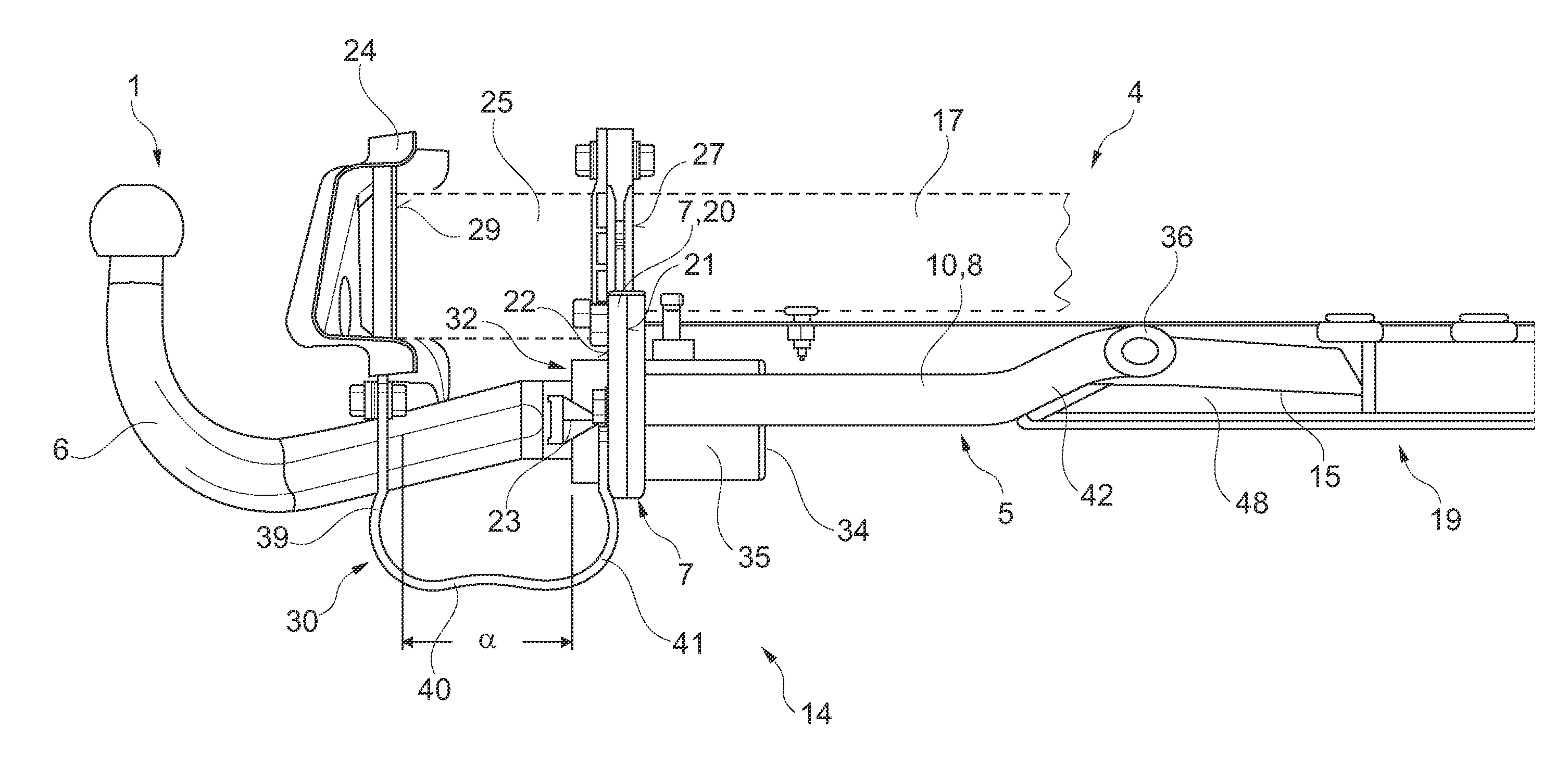
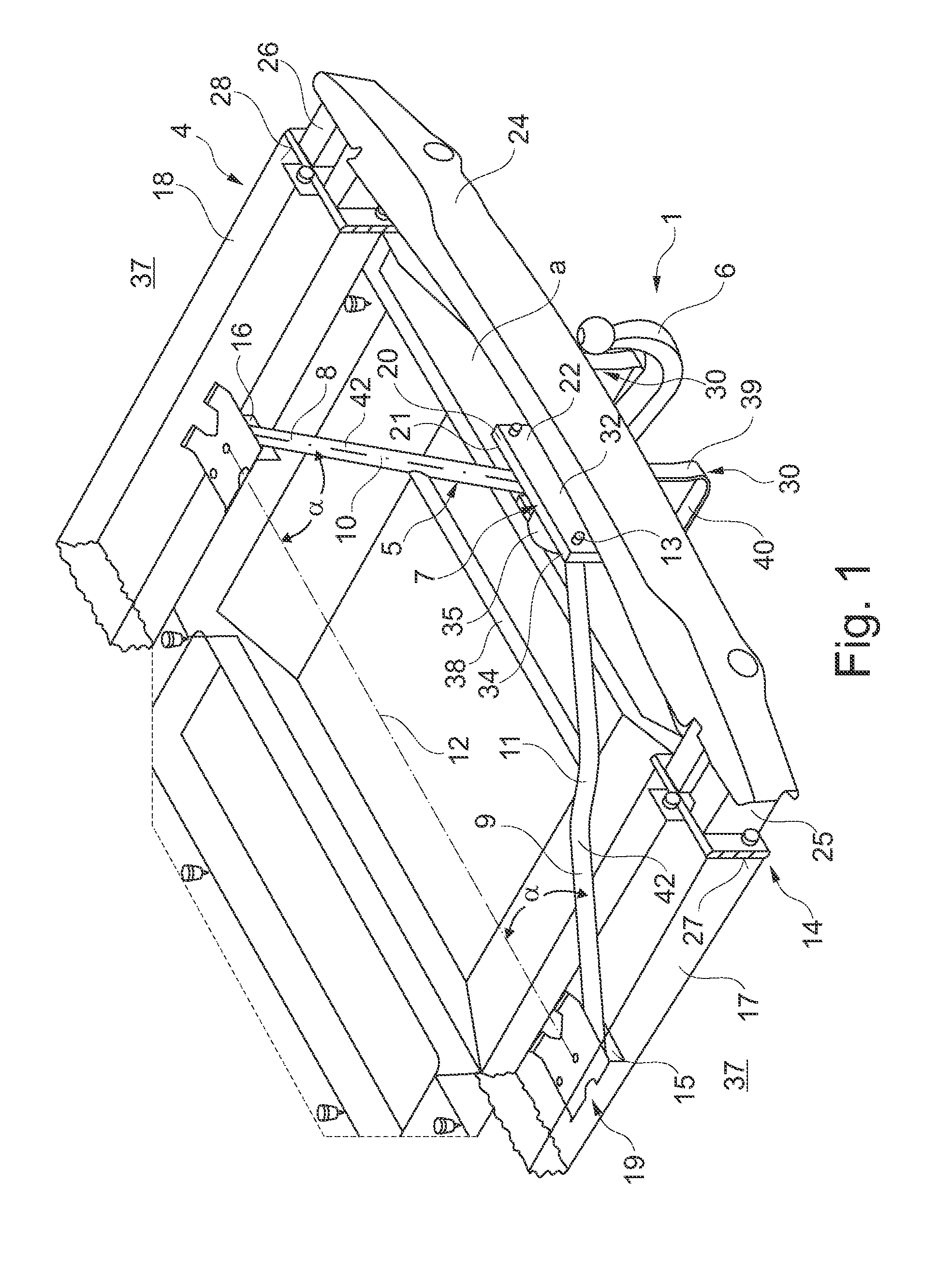
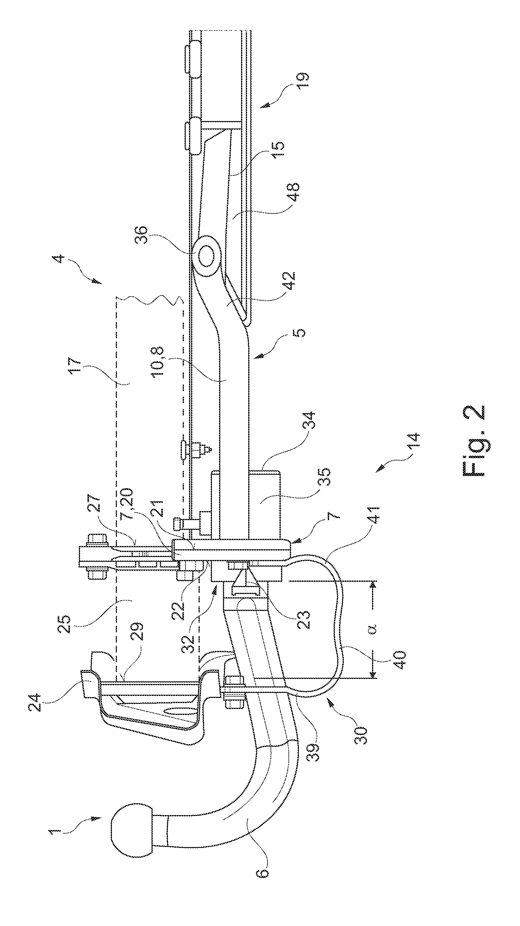
FIG. 1 shows a schematic perspective view of a tail of a passenger car 4 with a trailer towing device 1 according to a The trailer towing device 1 comprises a removable trailer coupling 6. This removable trailer coupling 6 is inserted in a latching opening 32 of a rear 22 of a central nodal element 7. This central nodal element 7 is arranged at a distance a from a rear bumper 24, which together with two crash boxes 25 and 26 forms a crumbling zone. This crumbling zone is to dampen an impact energy on the tail of the passenger car before the lateral side members 17 and 18, to whose ends 27 and 28 the crash boxes 25 and 26 are screwed, and the body of the vehicle are damaged. The distance a between the rear bumper 24 and the central nodal element 7 is so dimensioned that the crumbling zone length of the crash boxes 25 and 26 can be unimpededly utilized for the removal of the impact energy. Only after the compression of the crumbling zone length of the crash boxes 25 and 26 will the b...

second embodiment

FIG. 3 shows a schematic top view of a tail of a passenger car 4 with a trailer towing device 2 according to a This top view clearly shows the rear axle region 37 with the two rear wheelhouses 44 and 45 and the side members 17 and 18 as well as a further cross member 38 which connects the side members 17 and 18 in the front tail 19 and forms the cross member 38 for a Watt linkage. On the connecting points of the cross member 38 with the side members 17 and 18 the ends of the force transmission elements 8 and 9 of the traction force transmission linkage 5 which are not visible here are simultaneously fixed with the screw connections provided for the cross member 38.

The trailer load resting on the trailer coupling 6 in this embodiment is largely accepted by a connection with a cross member 46 comprising a luggage compartment lock 50, so that the spring-elastic connecting elements 30 known from FIG. 1 are merely provided optionally between the back side 29 of the rear bumper 24 and th...

third embodiment

FIG. 5 shows a schematic perspective bottom view of a tail of a passenger car 4 with trailer towing device 3 of the application. To this end, the traction force transmission linkage 5 is integrated with its two force transmission elements 8 and 9 as well as the transverse tube 36 in a floor plate 33 of the luggage compartment region, so that with this construction, too, the absorbing of the central nodal element s7 with the help of spring-elastic connecting elements to the rear bumper 24 is no longer required, since this is taken over by the rear front 47 of the floor structure 48 of the luggage compartment 49.

FIG. 6 shows a schematic partially longitudinally cut view of the trailer towing device 3 according to FIG. 5. The elements not located in the longitudinal section plane, such as the crash box 25, the side member 17 with its end 27, onto which the crash box 25 is flanged, are drawn with interrupted line. In the floor structure 48 both the transverse tube 36 as well as the forc...


PUM


Abstract

A trailer towing device of a passenger car is provided with a traction force transmission linkage and a removable trailer coupling. The removable trailer coupling is releasably fixed on a central nodal element of the transmission linkage. The transmission linkage includes, but is not limited to two force transmission elements that form two legs of a preferentially isosceles triangle. The tip of the triangle is arranged in a rear tail of the passenger car and comprises the central nodal element. The free ends of the legs are releasably connected to side members of the vehicle body in a front tail of the passenger car.

Description

CROSS-REFERENCE TO RELATED APPLICATIONThis application claims priority to German Patent Application No. 102010020648.2, filed May 15, 2010, which is incorporated herein by reference in its entirety.TECHNICAL FIELDThe technical field relates to a trailer towing device of a passenger car with a traction force transmission linkage and a removable trailer coupling. The removable trailer coupling is removably fixed to a central nodal element of the transmission linkage.BACKGROUNDA trailer towing device is known from the publication U.S. Pat. No. 6,348,112 B1, wherein the traction force transmission linkage consists of a cross beam, which is arranged in the tail transversely to the driving direction and comprises a central nodal element with which the removable trailer coupling is releasably fixed. At the ends of the cross member plate angles are arranged with which the cross member can be releasably fixed in end regions of side members of the vehicle body.This known trailer towing device...

Claims


Application Information

Patent Timeline
Patent Type & Authority Applications(United States)
IPC IPC(8): B60D1/14
CPCB60D1/06B60D1/52B60D1/485B60D1/143B60D1/167
Inventor LUNGERSHAUSEN, DIRK RAINERHEIM, GUNTHER
Owner GM GLOBAL TECH OPERATIONS LLC
Why Eureka
Try Eureka