Battery pack, discharge system, charge and discharge system, and discharge control method of lithium ion secondary battery

Inactive Publication Date: 2011-11-17
PANASONIC CORP
View PDF0 Cites 16 Cited by
  • Summary
  • Abstract
  • Description
  • Claims
  • Application Information

AI Technical Summary

Benefits of technology

[0019]According to the present invention, the end-of-discharge voltage of the lithium ion secondary battery is set on the basis of the detected use frequency (degree of deterioration) of the lithium ion secondary battery. As a result, it is possible to make adjustments such that the end-of-discharge voltage is set to a predetermined value X at an initial use period of the lithium ion secondary battery and that the end-of-discharge voltage is set to a predetermined value Y, which is lower than the predetermined value X, when the use frequency is a predetermined value or more. Therefore, in the initial use period of the lithium ion secondary battery, it is possible to prevent deterioration in the cycle characteristics of the lithium ion secondary battery by se

Problems solved by technology

The deterioration of the positive electrode may result in deterior

Method used


Image

  • Battery pack, discharge system, charge and discharge system, and discharge control method of lithium ion secondary battery
  • Battery pack, discharge system, charge and discharge system, and discharge control method of lithium ion secondary battery
  • Battery pack, discharge system, charge and discharge system, and discharge control method of lithium ion secondary battery

Examples


embodiment 1

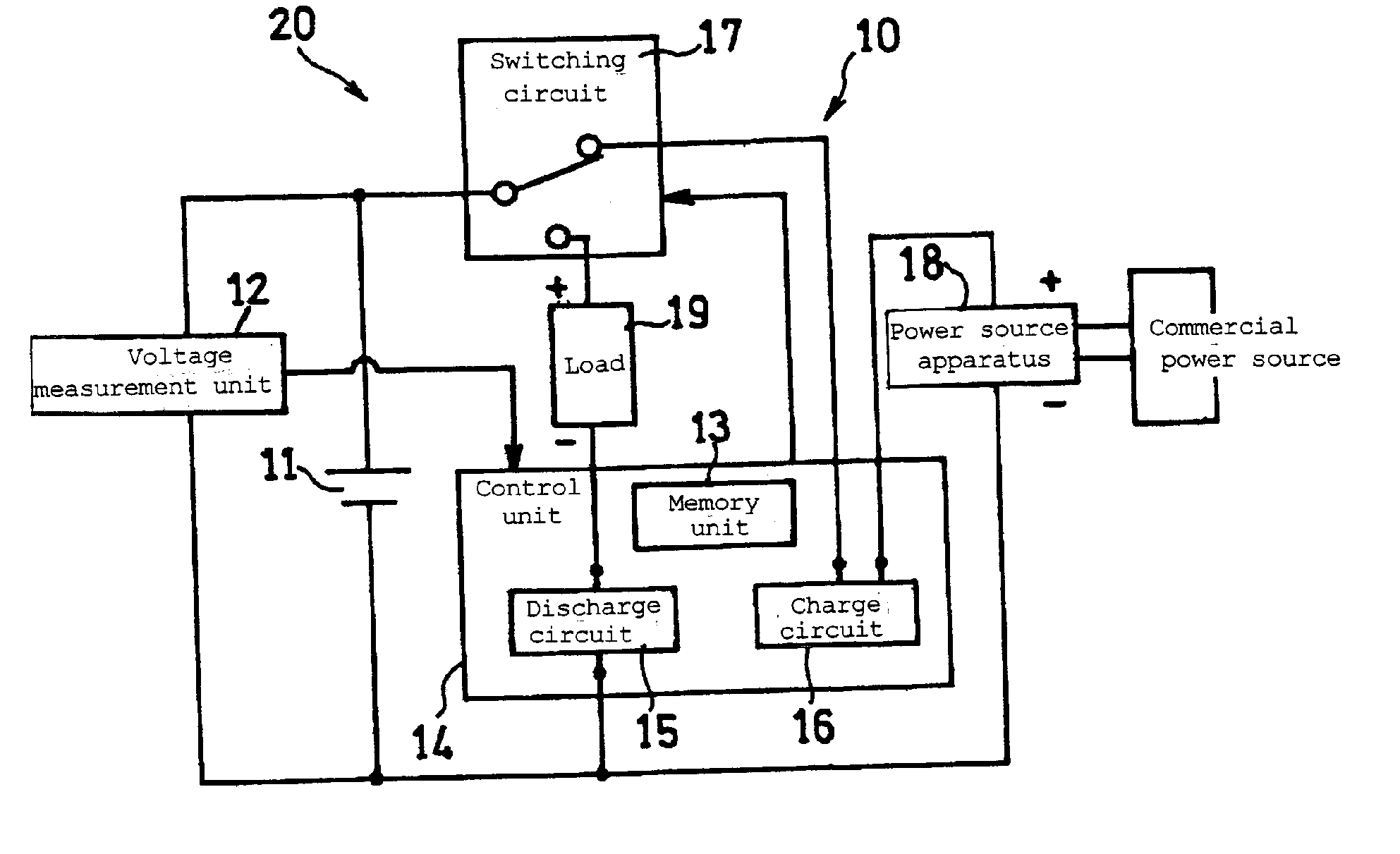
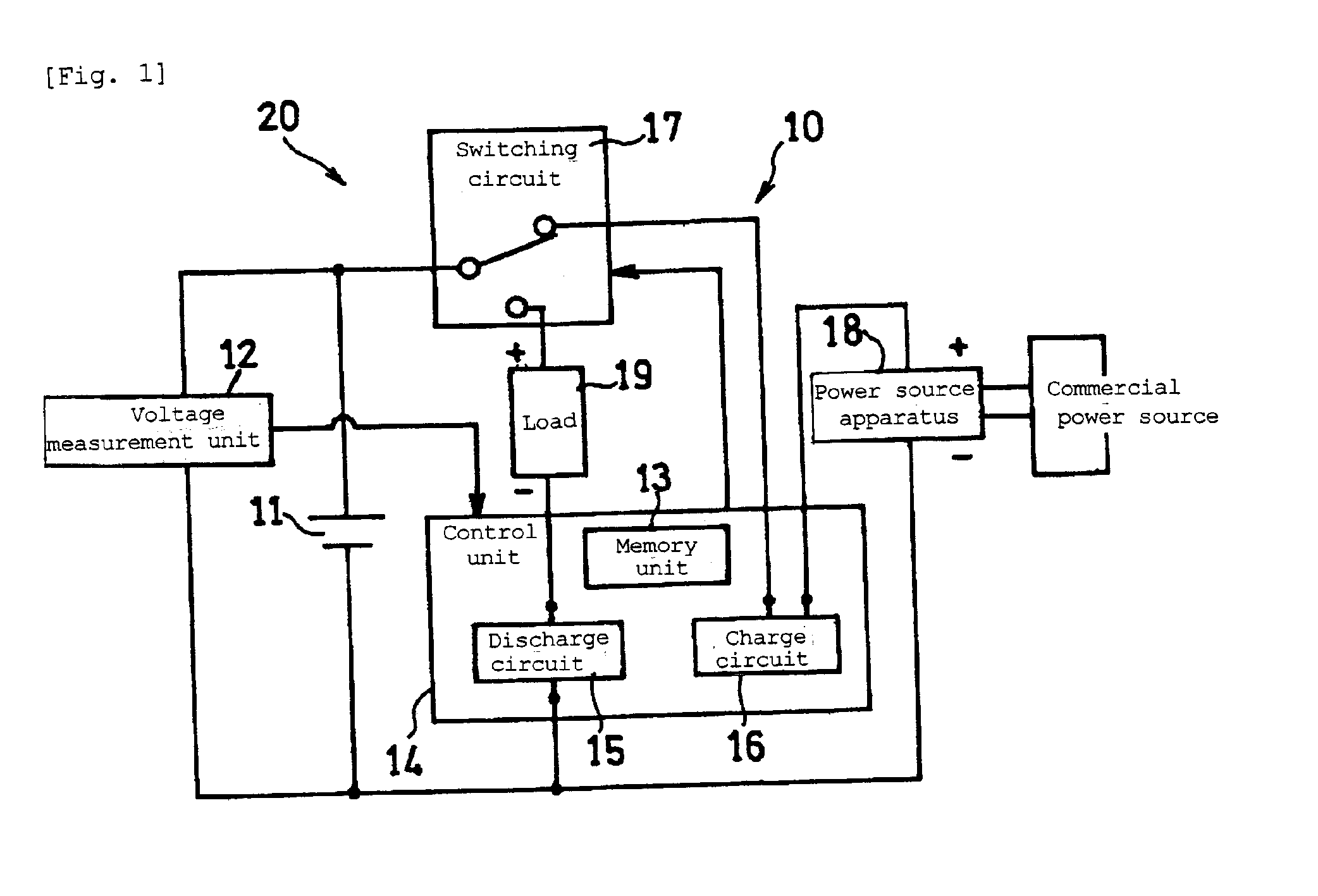
[0026]FIG. 1 is a circuit diagram illustrating a schematic configuration of a battery pack and a charge and discharge system including the battery pack in accordance with an embodiment of the present invention.

[0027]A battery pack 10 includes a lithium ion secondary battery (battery, hereinafter) 11, a voltage measurement unit 12 that detects terminal voltage of the battery 11, a control unit 14 that controls charge and discharge of the battery 11, and a switching circuit 17. The control unit 14 includes a memory unit 13, a discharge circuit 15, and a charge circuit 16. Although the control unit 14 serves both as a discharge control apparatus and as a charge control apparatus, the charge control apparatus may be configured as a component separate from the battery pack 10. Also, the charge circuit 16 may be included in the charge control apparatus which is a component separate from the battery pack 10. The voltage measurement unit 12 corresponds to a voltage measurement apparatus and...

embodiment 2

[0071]Next, Embodiment 2 of the present invention will be described. Since Embodiment 2 has the same configuration as that of Embodiment 1, drawings referred to in Embodiment 1 is used for explanation.

[0072]The difference of Embodiment 2 from Embodiment 1 is the point that the use frequency of the battery 11 is detected by the internal resistance, not by the difference of voltage ΔV1 between the open circuit voltage (OCV) and the closed circuit voltage (CCV).

[0073]As a method of detecting the internal resistance of the battery 11, there is a method of detecting the internal resistance by generating a predetermined pulse current from the battery 1 and detecting the internal resistance on the basis of a current value Ipul and a change amount ΔV2 in the terminal voltage (OCV) of the battery 11 measured by the voltage measurement unit 12. The ratio R of the change amount ΔV2 to the current value Ipul is compared with a predetermined value B from the relation of current×resistance=voltag...

embodiment 3

[0078]Next, Embodiment 3 of the present invention will be described. Since Embodiment 3 has the same configuration as that of Embodiment 1, drawings referred to in Embodiment 1 is used for explanation.

[0079]Embodiment 3 is different from Embodiment 1 in the point that the use frequency of the battery 11 is detected by the change of the open circuit voltage from the initial value.

[0080]As a method of detecting the use frequency of the battery 11 by the change of the open circuit voltage from the initial value, there is a method of comparing the open circuit voltage of the battery 11 in the same charged state (charge depth). For example, when the battery 11 is in the fully charged state, the open circuit voltage (OCVPV) of the battery 11 is measured, and the measured value OCVPV is compared with the open circuit voltage measured in the initial use period (OCVSV, initial open circuit voltage, hereinafter) of the battery 11 under the same conditions.

[0081]That is, a difference ΔV3 betwe...


PUM


Abstract

A battery pack includes at least a lithium ion secondary battery, a voltage sensor, and a control unit. The control unit controls discharge of the battery by a relatively high end-of-discharge voltage when the use frequency of the battery is relatively low during discharge of the battery. On the other hand, the control unit controls discharge of the battery by a relatively low end-of-discharge voltage when the use frequency of the battery is relatively high. Consequently, it is possible to prevent the utilizable capacity from decreasing more than a practical decrease in the capacity due to increase in the use frequency.

Description

TECHNICAL FIELD[0001]The present invention relates to a battery pack, and more specifically relates to control of charge and discharge of a battery pack including a lithium ion secondary battery.BACKGROUND ART[0002]In general, charge and discharge of a lithium ion secondary battery are performed within a predetermined voltage range. Specifically, the battery is charged until it reaches a predetermined end-of-charge voltage, and the battery is discharged until it reaches a predetermined end-of-discharge voltage. The charge and discharge are performed by a charge control unit and a discharge control unit in a battery pack or a charge and discharge system including the lithium ion secondary battery.[0003]Patent literature 1 proposes charging and discharging a lithium ion secondary battery including a lithium-containing manganese composite oxide in the positive electrode such that the terminal voltage is varied within the range of 1.5 V to 4.1 V. Consequently, deterioration of the posit...

Claims


Application Information

Patent Timeline
IPC IPC(8): H02J7/04
CPCH01M10/44H02J2007/0067H02J7/0063H01M10/48Y02E60/10H02J7/007182
Inventor YAMAMOTO, TAISUKEUGAJI, MASAYATAKEZAWA, HIDEHARUHIRAOKA, TATSUKI
Owner PANASONIC CORP
Why Eureka
Try Eureka