Transferring of 3D image data

a three-dimensional image and data transfer technology, applied in the field of three-dimensional (3d) image data transfer, can solve the problems of not having the option of manipulating the horizontal line synchronization pulse, the nave users of the stereoscopic 3d system described in the prior art do not properly recognize the swapping of left and right images,

Active Publication Date: 2011-11-17
KONINKLIJKE PHILIPS ELECTRONICS NV
View PDF10 Cites 23 Cited by
  • Summary
  • Abstract
  • Description
  • Claims
  • Application Information

AI Technical Summary

Benefits of technology

[0015]In an embodiment of the system the different frame types in the 3D video transfer format comprise at least one of a left frame type; a right frame type; a two dimensional [2D] frame type; a depth frame type; a transparency frame type; an occlusion frame type; a combination frame type indicative of a combination of sub-frames of said frame types; and the frame type synchronization indicator comprises frame type indicators corresponding to said frame types for synchronizing in time each of the 3D partial data structures from the respective frame types in the 3D video transfer format for generating the 3D display control signals. It is to be noted the above mentioned 2D frame type may be a center frame type, and the left and right frame types are also 2D frame types that may be used in combination with e.g. a depth frame or an occlusion frame type, and that many other combinations of the above frame types may effectively be employed to transfer 3D image data. The effect is that the various 3D video formats, which may range from a basic combination of left and right frame types for stereoscopic images, to complex 3D formats having a combination of left, right, depth, occlusion and transparency frames, are synchronized via the respective frame type synchronization indicators.
[0016]In an embodiment of the system the 3D video transfer format comprises a main video and at least one additional video layer transferred via respective frame types and the frame type synchronization indicator comprises at least one of a main frame type indicator and an additional layer frame type indicator. The effect is that the respective layers can be combined in any convenient way in the display device, while the combined image still maintains the correct timing relationship between the layers due to the frame type synchronization indicator. Advantageously the additional layer may comprise subtitles or graphical information like a menu or on screen display (OSD) generated in the source device, which can be combined with the main video information according to the capabilities of the display device.
[0017]In an embodiment of the system the frame type synchronization indicator comprises a 3D video format indicator indicative of the 3D video transfer format in a subsequent section of the 3D display signal. Advantageously such general 3D format indicator allows sudden changes of the video stream like jumps or mode changes in the source device to be immediately followed by the display device.
[0018]In an embodiment of the system the frame type synchronization indicator comprises a frame sequence indicator indicative of a frequency of at least one frame type and / or an order of the different frame types. The effect is that different frame types may be multiplexed at different frame frequencies and / or in a predefined order, while the respective order or sequence is detectable in the display device. Hence the display device will be aware of the sequence of frames that will be transferred, and can adjust the processing resources accordingly.

Problems solved by technology

However, in particular for interlaced video signals, there are no options for manipulating the horizontal line synchronization pulses.
A problem that occurs with current systems as mentioned above is that there is no absolute synchronization of the left and right video frames with the shutter glasses.
We have found that naïve users of a stereoscopic 3D system as described in the prior art do not properly recognize when the left and right images are swapped.
This can be very problematic as this can lead to severe eye strain and even nausea.
If such a system were widely employed now it would cause confusion amongst consumers and severely hinder adoption of the technology.
Hence the known 3D display signal cannot be used for transferring various digital 3D image signals for consumer use.

Method used


Image

  • Transferring of 3D image data
  • Transferring of 3D image data
  • Transferring of 3D image data

Examples


Embodiment Construction

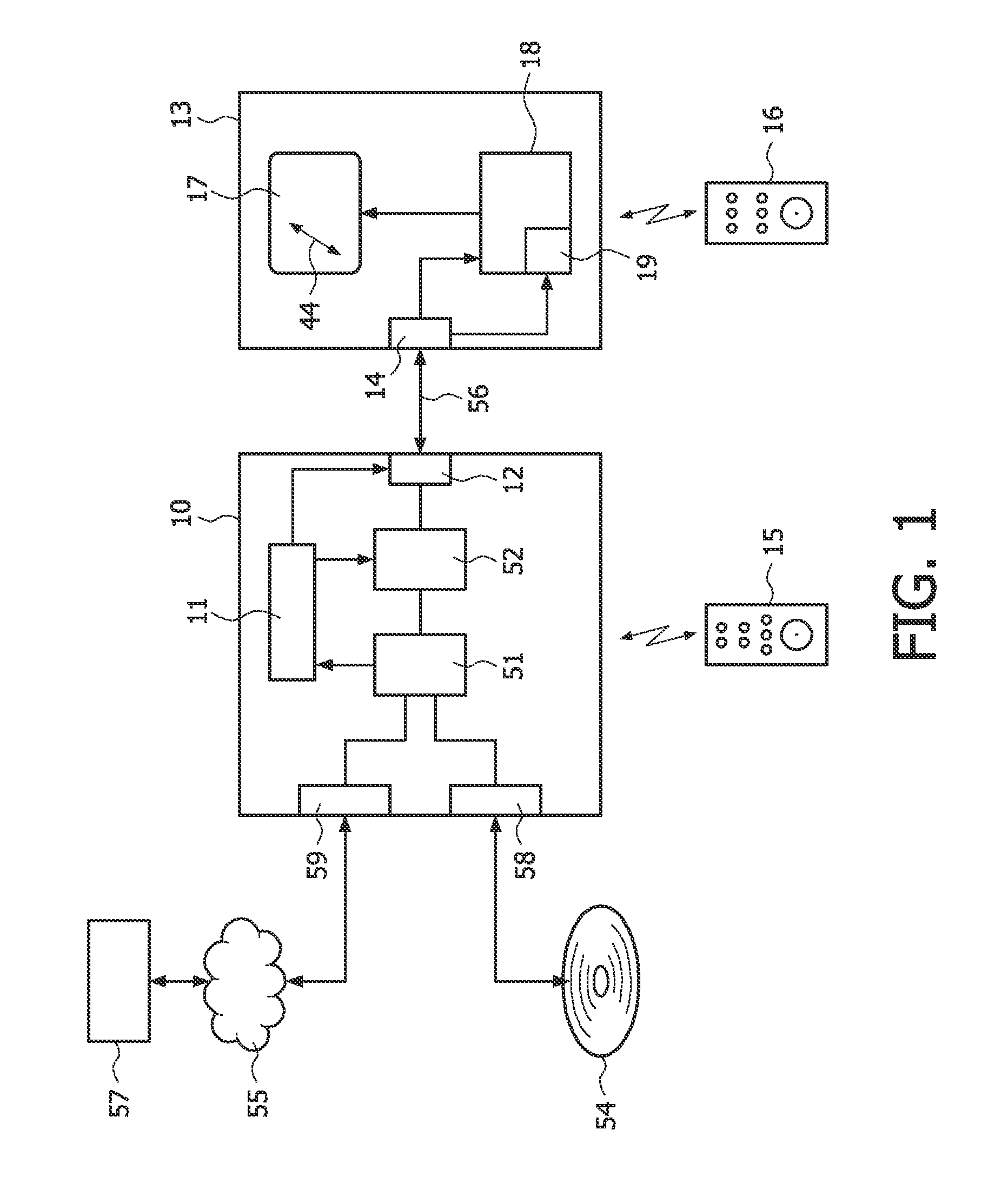
[0029]FIG. 1 shows a system for transferring three dimensional (3D) image data, such as video, graphics or other visual information. A 3D source device 10 is coupled to a 3D display device 13 for transferring a 3D display signal 56. The 3D source device has an input unit 51 for receiving image information. For example the input unit device may include an optical disc unit 58 for retrieving various types of image information from an optical record carrier 54 like a DVD or BluRay disc. Alternatively, the input unit may include a network interface unit 59 for coupling to a network 55, for example the internet or a broadcast network, such device usually being called a set-top box. Image data may be retrieved from a remote media server 57. The source device may also be a satellite receiver, or a media server directly providing the display signals, i.e. any suitable device that outputs a 3D display signal to be directly coupled to a display unit.

[0030]The 3D source device has a processing...


PUM


Abstract

A system of transferring of three dimensional (3D) image data is described. A 3D source device (10) provides 3D display signal (56) for a display (13) via a high speed digital interface like HDMI. The 3D display signal has frames constituting the 3D image data according to a 3D video transfer format, in which format the frames comprise at least two different frame types. Each frame has a data structure for representing a sequence of digital image pixel data, and represents a partial 3D data structure. The 3D source device includes frame type synchronization indicators in the 3D display signal. The display detects the frame type synchronization indicators and frame types, and generates the display control signals based on synchronizing the partial 3D data structures in dependence of the frame type synchronization indicators.

Description

FIELD OF THE INVENTION[0001]The invention relates to a method of transferring of three dimensional (3D) image data, the method comprising, at a 3D source device, processing source image data to generate a 3D display signal, the 3D display signal comprising frames constituting the 3D image data according to a 3D video transfer format, in which format the frames comprise at least two different frame types, and outputting the 3D display signal; and, at a 3D display device, displaying the 3D image data on a 3D display, receiving the 3D display signal, and detecting the different frame types in the received 3D display signal, and generating display control signals for rendering the 3D image data on the 3D display based on the different frame types.[0002]The invention further relates to the above mentioned 3D source device, the 3D display signal and the 3D display device.[0003]The invention relates to the field of transferring, via a high-speed digital interface, e.g. HDMI, three-dimensio...

Claims


Application Information

Patent Timeline
Patent Type & Authority Applications(United States)
IPC IPC(8): H04N13/00H04N13/04
CPCH04N13/0048H04N13/0051H04N13/0059H04N2213/003H04N13/007H04N13/0438H04N13/0066H04N13/161H04N13/167H04N13/178H04N13/183H04N13/194H04N13/341G06T15/20H04N13/00
Inventor NEWTON, PHILIP S.VAN DER HEIJDEN, GERARDUS W.T.
Owner KONINKLIJKE PHILIPS ELECTRONICS NV
Why Eureka
Try Eureka