
Apparatus for directing air flow in a biological safety cabinet

a biological safety cabinet and apparatus technology, applied in the field of apparatus for directing air flow in the biological safety cabinet, can solve the problems of contaminating procedures conducted in the work chamber, hazard to users and other laboratory personnel, etc., to avoid the potential for cross-contamination, promote the laminar flow of the circulating air, and enhance the aerodynamics of the intake air flow

Inactive Publication Date: 2011-11-17
KEWAUNEE SCI
View PDF37 Cites 9 Cited by
  • Summary
  • Abstract
  • Description
  • Claims
  • Application Information

AI Technical Summary

Benefits of technology

[0006]The present invention seeks to meet the foregoing objectives in an improved manner over conventional biological safety cabinets. Basically, the present invention provides a biological safety cabinet comprising a housing defining a work chamber, a filtration chamber, and a forward opening into the work chamber for user access. An air recirculation system circulates internal air within and between the work chamber and the filtration chamber in a controlled manner for mitigating escape of circulating internal air from the work chamber and for mitigating ingress of ambient air into the work chamber through the forward opening. The air recirculation system includes a filter between the filtration chamber and the work chamber for removing contaminants from the air before re-entering the work chamber. More specifically, the air recirculation system includes an air exhaust sub-system for discharge of a portion of the internal air from the filtration chamber and an air intake sub-system for directing make-up ambient air into the filtration chamber for replacement of the exhausted internal air, and the air intake sub-system includes an intake opening disposed adjacent the forward opening.
[0008]According to a further aspect of the present invention, the housing is supported on a stand at an elevation suitable for user access into the work chamber through the forward opening, and a user arm rest is affixed to the support stand extending alongside the forward opening at a spacing outwardly from the housing to avoid the potential for cross-contamination between the arm rest and the work chamber. The arm rest is disposed adjacent the air intake grille at an outward spacing therefrom and has an aerodynamic configuration for assisting in direction of ambient make-up air to the make-up air intake surface. Preferably, the arm rest is of a generally elliptical shape to enhance the aerodynamics of intake air flow thereover.
[0009]The housing also includes a transverse air transmission grille between the work chamber and the filtration chamber, and a sash forwardly and downwardly of the grille for defining a forward boundary to the work chamber. According to another aspect of the present invention, the grille has a generally flat main extent terminating at a spacing from the sash and an upwardly angled extent adjacent the sash. Both the main extent and the angled extent of the grille are perforated for passage of internal air circulating through the filter from the filtration chamber into the work chamber, the angled extent of the grille being effective to direct an increased flow of circulating internal air downwardly along the sash to promote laminar flow of the circulating air therealong.

Problems solved by technology

This is especially important in the forward area of the work chamber in the region of the user access opening, as turbulence in the air currents in this region can result in undesirable escape of contaminated internal air outwardly through the access opening, posing a hazard to users and other laboratory personnel, and / or ingress of unfiltered ambient air into the work chamber, posing a risk of contaminating procedures conducted within the work chamber.

Method used


Image

  • Apparatus for directing air flow in a biological safety cabinet
  • Apparatus for directing air flow in a biological safety cabinet
  • Apparatus for directing air flow in a biological safety cabinet

Examples


Embodiment Construction

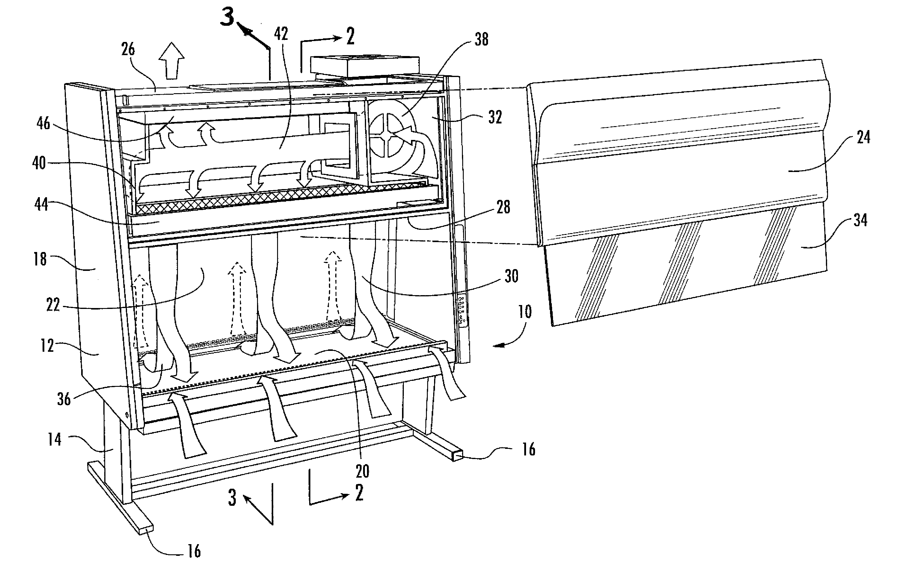
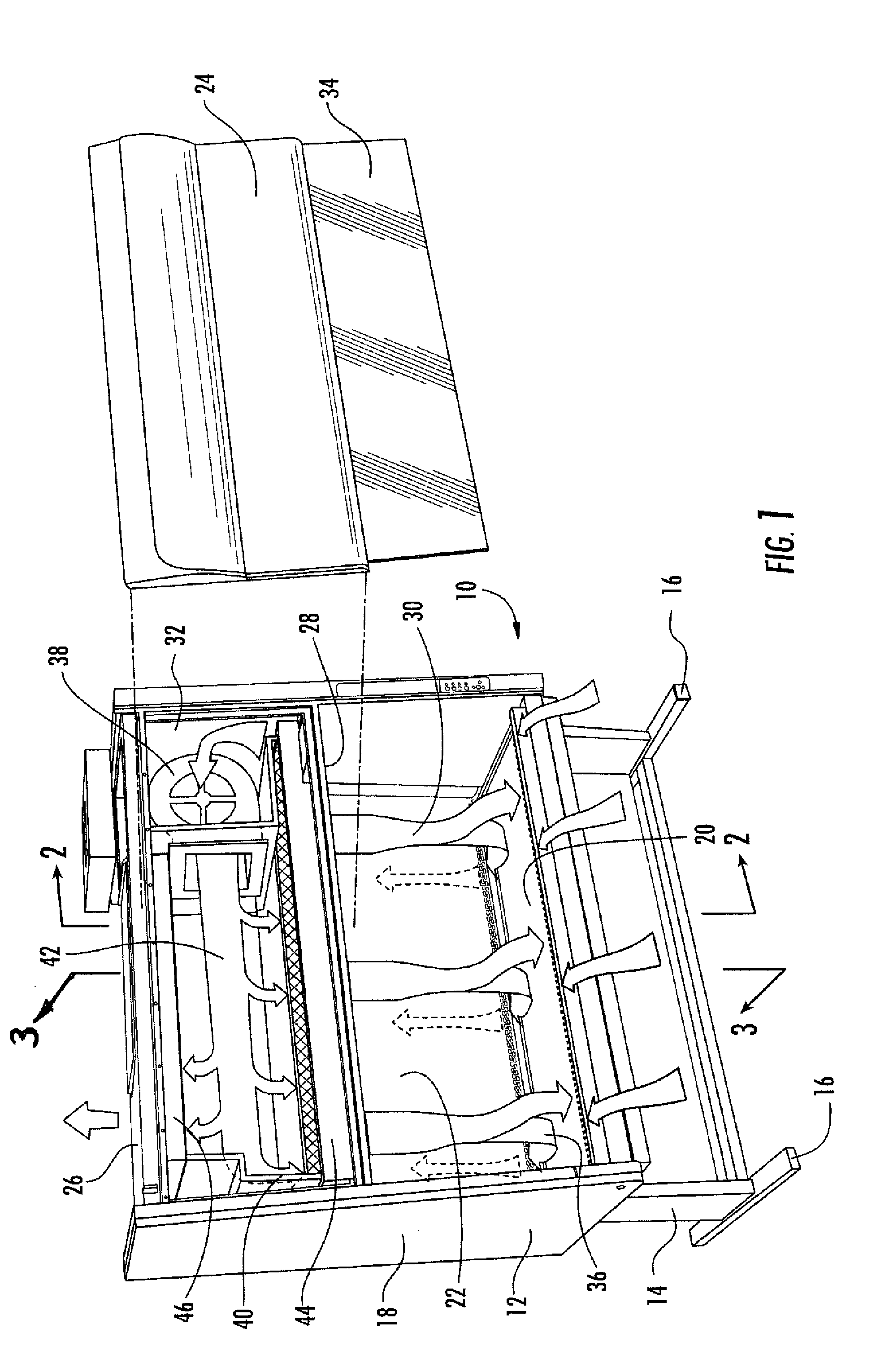
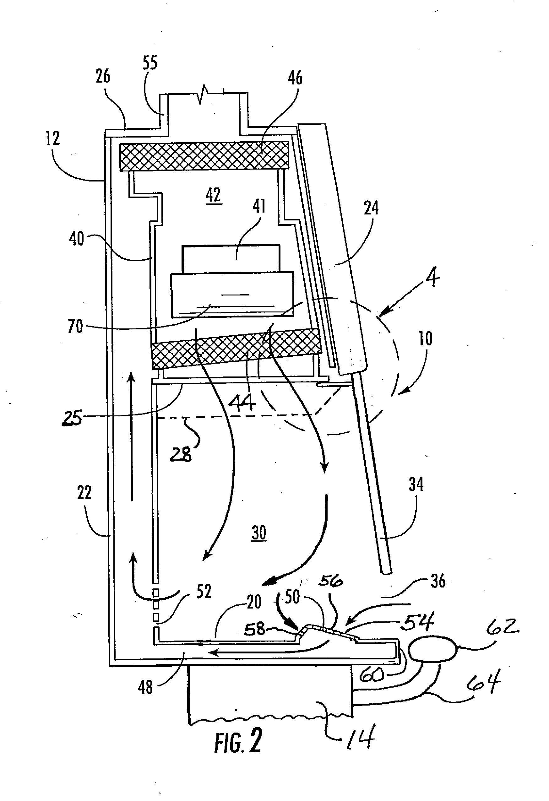
[0014]Referring now to the accompanying drawings, and initially to FIG. 1, a biological safety cabinet in accordance with one preferred embodiment of the present invention is indicated generally at 10. The safety cabinet 10 basically comprises a housing 12 supported on a trestle stand 14, which may include a set of casters 16 for moveability of the cabinet structure. The housing 12 is a generally rectangular structure having spaced-apart end walls 18, a bottom wall 20, a rear wall 22, a partial front wall 24, and a top wall 26, collectively defining an open interior which is divided by a horizontal intermediate filter structure 25, 28, 44 (see also FIGS. 2 and 4) into a lower work chamber 30 and an upper air recirculation chamber 32. The housing 12 may preferably be fabricated of sheet metal, such as stainless steel.

[0015]The partial front wall 24 predominately encloses only the air recirculation chamber 32, leaving open front access by users into the work chamber 30. A transparent ...


PUM


Abstract

A biological safety cabinet with several air flow directional control enhancements. A perforated air intake grille within the work chamber inwardly adjacent the user access opening has a forwardly facing make-up air intake surface and a rearwardly facing internal air intake surface angled in converging relation to promote a physical division between intake of ambient air and internal air into the cabinet's air recirculation system. An aerodynamic user arm rest is affixed to a support stand to extend alongside the access opening at a spacing outwardly from the housing to assist in directing make-up air to the ambient air intake opening without cross-contamination between the arm rest and the work chamber. An air transmission grille above the work chamber has a horizontal main extent terminating at a spacing from the sash and an upwardly angled extent adjacent the sash to direct increased laminar air flow downwardly along the sash.

Description

BACKGROUND OF THE INVENTION[0001]The present invention relates generally to biological safety cabinets and, more particularly, to structural elements of biological safety cabinets by which the flow of air is directed within biological safety cabinets.[0002]Biological safety cabinets provide a biohazard containment means which enable laboratory personnel in diverse industries, e.g., life science, medical, and pharmaceutical industries, to perform various laboratory, experimental and like procedures utilizing biologically hazardous substances while protecting the personnel, the work product and the ambient environment from exposure to and contamination by such substances. Biological safety cabinets are currently certified by the National Sanitation Foundation (NSF) International, of Ann Arbor, Mich., according to three levels of classification. The present invention is particularly applicable to the class of biological safety cabinets referred to as Class II, Type A2 cabinets.[0003]Cl...

Claims


Application Information

Patent Timeline
IPC IPC(8): B08B15/02
CPCB08B2215/003B08B15/023
Inventor HAUGEN, ROBERT KENNETHRAMOS, ARTURORINDOKS, KURT P.
Owner KEWAUNEE SCI
Learn More