Electric Motor Assist Bicyle

a technology of electric motors and bicycles, applied in the direction of electric devices, machines/engines, magnetic circuit shapes/forms/construction, etc., can solve the problems of limited range, limited capacity, and most bicycles could only be pedaled with difficulty, so as to improve the appearance of the bicycle, reduce the effect of connective losses and increase heat dissipation

Inactive Publication Date: 2011-11-24
RITTENHOUSE NORMAN
View PDF11 Cites 21 Cited by
  • Summary
  • Abstract
  • Description
  • Claims
  • Application Information

AI Technical Summary

Benefits of technology

[0026]The electric bicycle hub motor includes plural cascaded Hall effect sensors located near the path of the rotor permanent magnets to generate a stair step sine wave which conveys information on rotor speed, direction, and timing to the electronic controller, and for generating an output waveform for driving the parallel pole direct drive motor. The electrical assist bicycle can have side plates that form a band around the parallel pole direct drive motor, the band holding the side plates in compression and drilled for installation of spokes to alleviate the need for through fasteners and the side plates can include a threaded flange to install a chain sprocket assembly or a belt pulley assembly.
[0027]The stator assembly can be used to recharge batteries when decelerating or riding downhill, the cylindrical rechargable batteries can be stacked together for placement within the down tube or seat tube of the bicycle frame, and a battery terminal lead connected at one end with the stack of rechargable batteries can be routed through the crank arm housing to the electronic controller to minimize connective losses and to improve the appearance of the bicycle. There can be a battery access port in the bicycle crank arm housing for installing and removing the stack of rechargeable batteries which can have weatherproof access covers for the crank arm housing. A longitudinal spring can be used to hold the cylindrical battery stack in contact with the interior wall of the down tube or seat tube to increase heat dissipation and reduce rattling and the batteries can be in a a tubular housing to hold the stack of rechargable batteries or have shrink wrap material wrapped around the stack of rechargeable batteries to insulate, protect and maintain the shape of the stack of rechargeable batteries.

Problems solved by technology

Most could only be pedaled with difficulty over short distances on level ground.
Electrically-powered bicycles use batteries, which have a limited capacity and thus a limited range, particularly when large amounts of power are utilized.
This design limitation means that the use of the electric motor as an assist to pedal propulsion is more emphasized than is the case with an internal combustion engine.

Method used


Image

  • Electric Motor Assist Bicyle
  • Electric Motor Assist Bicyle
  • Electric Motor Assist Bicyle

Examples


Embodiment Construction

[0048]Before explaining the disclosed embodiments of the present invention in detail it is to be understood that the invention is not limited in its application to the details of the particular arrangements shown since the invention is capable of other embodiments. Also, the terminology used herein is for the purpose of description and not of limitation.

[0049]The following is a list of the reference numbers used in the drawings and the detailed specification to identify components:

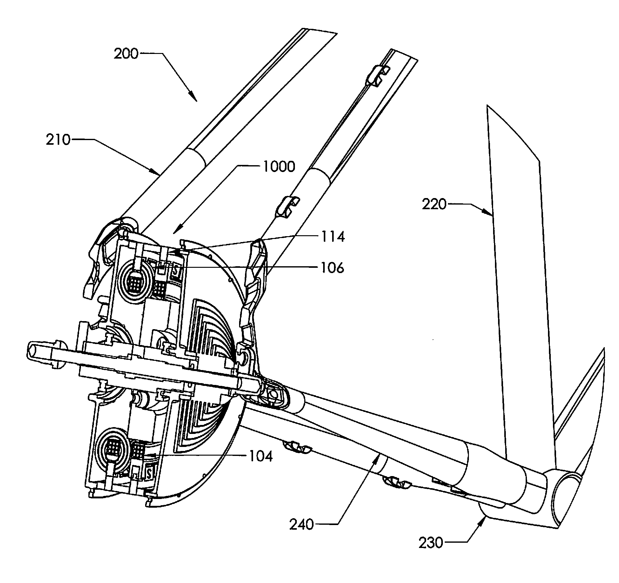
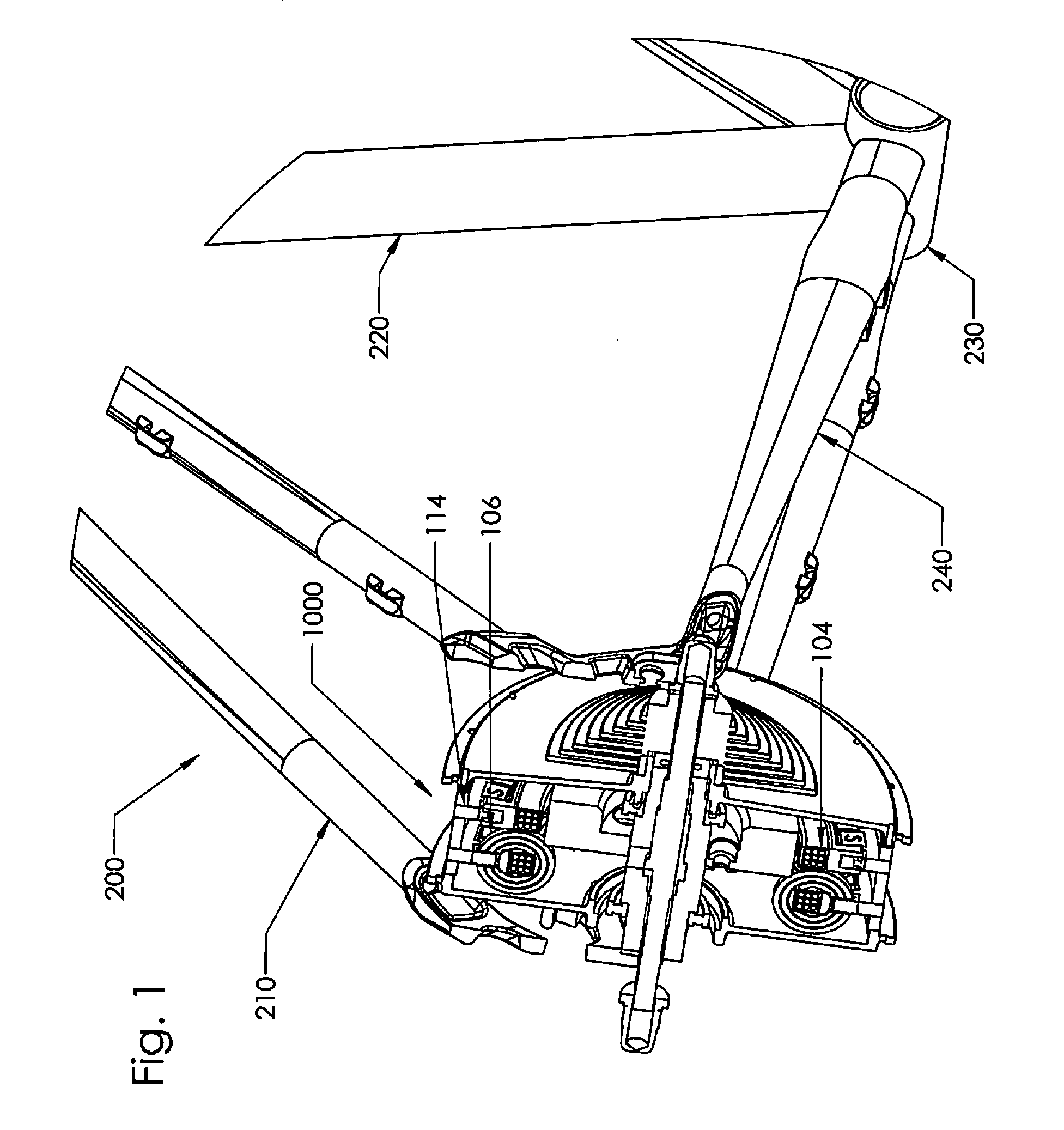
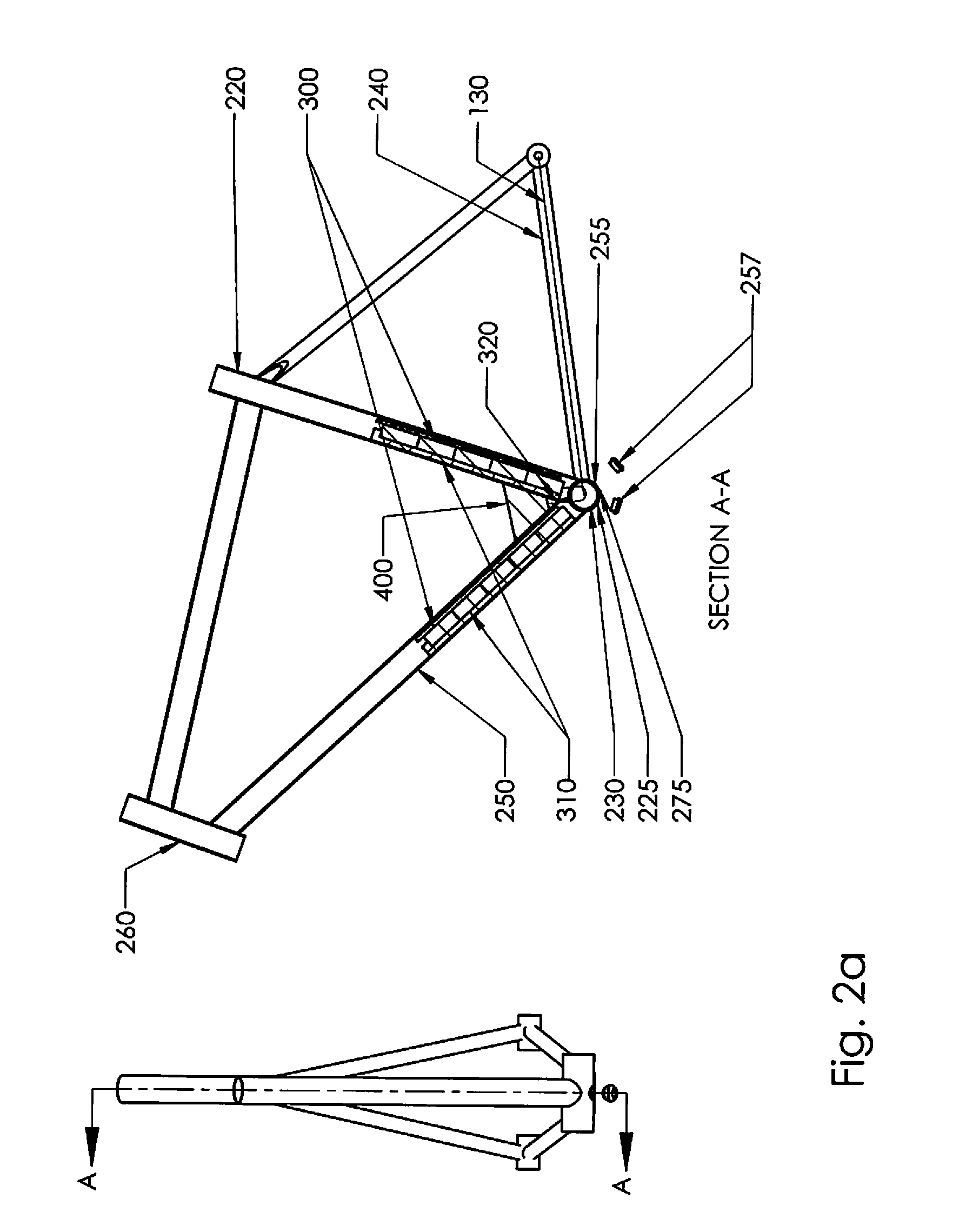
1000bicycle hub motor 100inert stator form 230crank arm housing 101tooth / teeth 240chain stay 102alignment hole 250down tube 103assembled winding bobbin 255down tube access 104transverse winding 257access plug 105winding bobbin 260steering head 106wound magnetic flux channels 270strain gauge 110hub 275strain gauge wiring 112pole piece 300battery 120hub 310spring 130motor-electronic wiring 320battery interface wiring 200bicycle frame 330spacer spring 210rear fork / seat stay 400control electronics 220seat tube...


PUM


Abstract

Methods, systems and apparatus for an electric motor assist bicycle having a hub motor mounted to the front or rear hub to provide electric motor assist, and to function as a generator to charge batteries. The motor can be either a molded or wound magnetic flux channel transverse wound stator permanent magnet motor. The bicycle hub motor includes an electronic controller mounted to the frame of the bicycle and coupled with feedback electronics for monitoring a timing, speed and direction and coupling a signal to a processing unit for adjusting the drive electronics driving the phase windings. The pedal crank arm housing of the electric motor assist bicycle can include battery access ports with batteries stacked inside the bicycle seat tube and the down tube and a strain gauge to measure the rider pedaling effort and produce a signal in response.

Description

[0001]This application is a continuation-in-part of U.S. application Ser. No. 12 / 784,690 filed on May 21, 2010 which is a continuation-in-part of U.S. application Ser. No. 12 / 486,957 filed on Jun. 18, 2009, now U.S. Pat. No. 7,868,510, which is a continuation-in-part of U.S. application Ser. No. 12 / 371,823 filed on Feb. 16, 2009, now U.S. Pat. No. 7,723,891, which is a divisional application of U.S. application Ser. No. 11 / 731,427 filed on Mar. 30, 2007, now U.S. Pat. No. 7,492,074.FIELD OF THE INVENTION[0002]This invention relates to motorized bicycles and, in particular, to methods, systems, devices and apparatus for an electric motor assist bicycle having a hub motor mounted to the front or rear hub to provide electric motor assist, and to function as a generator to charge batteries, the motor being one of a molded or wound magnetic flux channel transverse wound stator permanent magnet motor.BACKGROUND AND PRIOR ART[0003]As early as 1903, motorized bicycles were being fitted with...

Claims


Application Information

Patent Timeline
Patent Type & Authority Applications(United States)
IPC IPC(8): H02P7/00H02K1/02B62J6/12
CPCB60L7/14Y02T10/642B60L11/1803B60L11/1874B60L11/1877B60L2200/12B60L2220/44B62M6/65B62M6/90H02K7/14H02K11/048H02K21/125H02K2201/12Y02T10/641Y02T10/7005Y02T10/705H02P6/142H02P6/182B60L11/007H02P6/15B60L50/20B60L50/51B60L58/26B60L50/66Y02T10/64Y02T10/70H02M7/00
Inventor RITTENHOUSE, NORMAN
Owner RITTENHOUSE NORMAN
Why Eureka
Try Eureka