Charge Equalization Apparatus for Series-Connected Battery String Using Regulated Voltage Source

a series-connected battery and equalization apparatus technology, applied in the direction of charge equalization circuit, transportation and packaging, arrangement of several simultaneous batteries, etc., can solve the problems of increasing reducing productivity, and reducing the number of components. , the effect of reducing the complexity and volume of the charge equalization apparatus

Active Publication Date: 2011-11-24
SK ON CO LTD +1
View PDF4 Cites 57 Cited by
  • Summary
  • Abstract
  • Description
  • Claims
  • Application Information

AI Technical Summary

Benefits of technology

[0029]The automatic charge equalization apparatus using a regulated voltage source according to the present invention has advantages in that expensive parts such as the sensing unit sensing individual voltage of the battery and the analog-digital converter are not needed since charge equalization is performed by connecting the regulated voltage source with each battery successively, and the number of components can be markedly reduced and thus complexity and volume of the charge equalization apparatus are reduced and the production cost is reduced as the battery belonging to each battery module shares the regulated voltage source via the bidirectional switch unit.
[0030]Further, it is possible to structure the charge equalization apparatus flexibly and easily even the number of total batteries is changed by dividing the total battery string into battery modules and providing the bidirectional switch unit and the regulated voltage source for each module, to cope with degradation and damage of the components caused due to long-term usage, and to use low voltage bidirectional switch having low internal voltage in order to structure the bidirectional switch unit. Further, it is possible to output the regulated voltage using the DC-DC converter having low capacity.

Problems solved by technology

However, even though the batteries produced via the typical manufacturing method have the same structure using the same anode, cathode and electrolyte, there is existed a difference in charge or discharge characteristics between each battery connected in series.
Therefore, since a voltage difference exists between the unit batteries when using the batteries connected in series, there are problems in that a total voltage (total voltage of batteries connected in series) becomes zero so that a recharge is needed even though one battery is totally discharged irrespective of voltage of the other batteries in the unit batteries connected in series, the battery reaching the certain voltage at first is overcharged due to different voltage between each battery even at the time of the recharge, and the battery which still does not reach any certain voltage exists even though some batteries are overcharged.
Further, if the number of charging / discharging times is higher, significant degradation can occur in materials composing the battery so that characteristics of the battery become different and such degradation is responsible for aggravating the difference between the individual cells.
However, since the above-mentioned charge equalization apparatuses have a charge equalization apparatus provided in each of the batteries connected in series so that charging or discharging is performed separately on each battery and each voltage of the batteries is measured and converted to the digital value separately to determine whether or not to charge or discharge the battery and to set charge equalization conditions based on the voltage of the battery, there are problems that complexity and volume of the charge equalization apparatus are increased and thus productivity is reduced and production cost is higher, and components composing the charge equalization apparatus or the switch module for controlling it must endure higher voltage stress.

Method used


Image

  • Charge Equalization Apparatus for Series-Connected Battery String Using Regulated Voltage Source
  • Charge Equalization Apparatus for Series-Connected Battery String Using Regulated Voltage Source
  • Charge Equalization Apparatus for Series-Connected Battery String Using Regulated Voltage Source

Examples


Embodiment Construction

[0038]Hereinafter, a charge equalization apparatus and method according to the present invention will be described in detail with reference to accompanying drawings. The accompanying drawings are provided as an example sufficiently to deliver an idea of the present invention to the person skilled in the art. Therefore, the present invention is not bounded by the drawings presented hereinafter but can be specified in another form. Further, like reference numerals denote like element throughout the following detailed description of the invention.

[0039]At this time, if the technological terms and science terms used herein do not have any other definition, they have meanings that can be typically understood by the person skilled in the art. Further, known functions and structures which can unnecessary make obscure the subject matter of the present invention in the following description and accompanying drawings will be omitted.

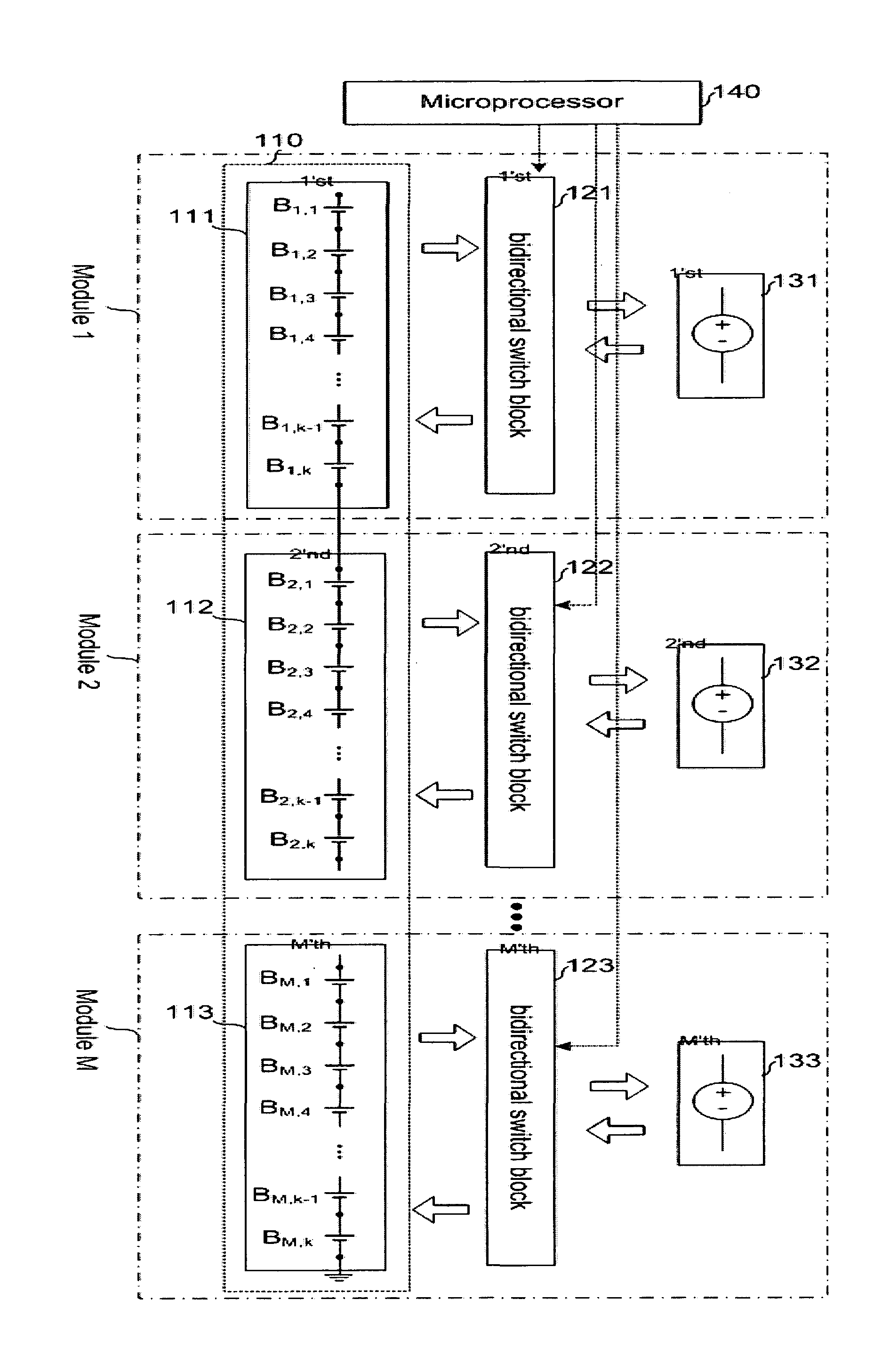
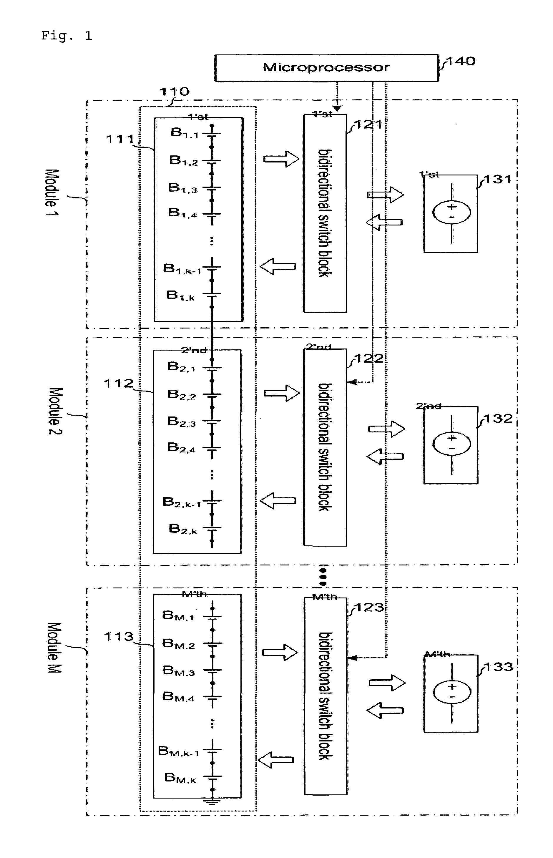
[0040]FIG. 1 shows one example of an automatic charge equali...


PUM


Abstract

An automatic charge equalization apparatus using a regulated voltage source according to the present invention comprises a battery module having a plurality of batteries connected in series; a battery string having M (natural number of M≧2) battery modules connected in series: a regulated voltage source which is provided for each battery module and outputs and maintains an average voltage of the battery string; a bidirectional switch block which is provided for each battery module between the battery module and the regulated voltage source to connect each battery to an output of the regulated voltage source by forming a parallel current moving path to each battery composing the battery module; and a microprocessor controlling the bidirectional switch block, wherein each battery composing the battery module shares the regulated voltage source by the bidirectional switch block and the microprocessor controls the bidirectional switch block to successively connect the batteries composing the battery module with the regulated voltage source.

Description

TECHNICAL FIELD[0001]The present invention relates to a charge equalization apparatus for series-connected battery string, and more particularly to a charge equalization apparatus using simple circuits without using a voltage sensing unit measuring a voltage of the battery and an analog-digital converter.BACKGROUND ART[0002]If a voltage higher than a reference voltage of a unit battery (cell) is needed such as in a hybrid vehicle which uses a lithium ion cell as a power source, it is typical to connect a plurality of unit batteries in series. However, even though the batteries produced via the typical manufacturing method have the same structure using the same anode, cathode and electrolyte, there is existed a difference in charge or discharge characteristics between each battery connected in series.[0003]Therefore, since a voltage difference exists between the unit batteries when using the batteries connected in series, there are problems in that a total voltage (total voltage of b...

Claims


Application Information

Patent Timeline
Patent Type & Authority Applications(United States)
IPC IPC(8): H02J7/04H02J7/02
CPCH02J7/0019
Inventor LIM, JAE HWANPARK, SANG HYUNLEE, JOONG HUIMOON, GUN-WOOPARK, HONG-SUNKIM, CHOL-HO
Owner SK ON CO LTD
Why Eureka
Try Eureka