Projection optical system and projection type display using the same
a projection optical system and optical axis technology, applied in the direction of microscopes, telescopes, instruments, etc., can solve the problem of missing parts outside the effective area of the lens, and achieve the effect of reducing the distance between the image plane on the screen and reducing the size of the apparatus in the direction of the optical axis of the first optical system, and reducing the size of the apparatus in the direction of the optical axis of the firs
- Summary
- Abstract
- Description
- Claims
- Application Information
AI Technical Summary
Benefits of technology
Problems solved by technology
Method used
Image
Examples
first example
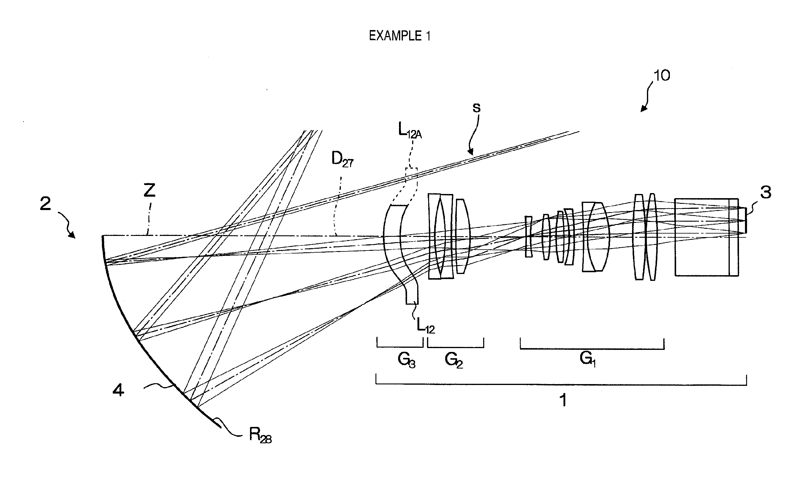
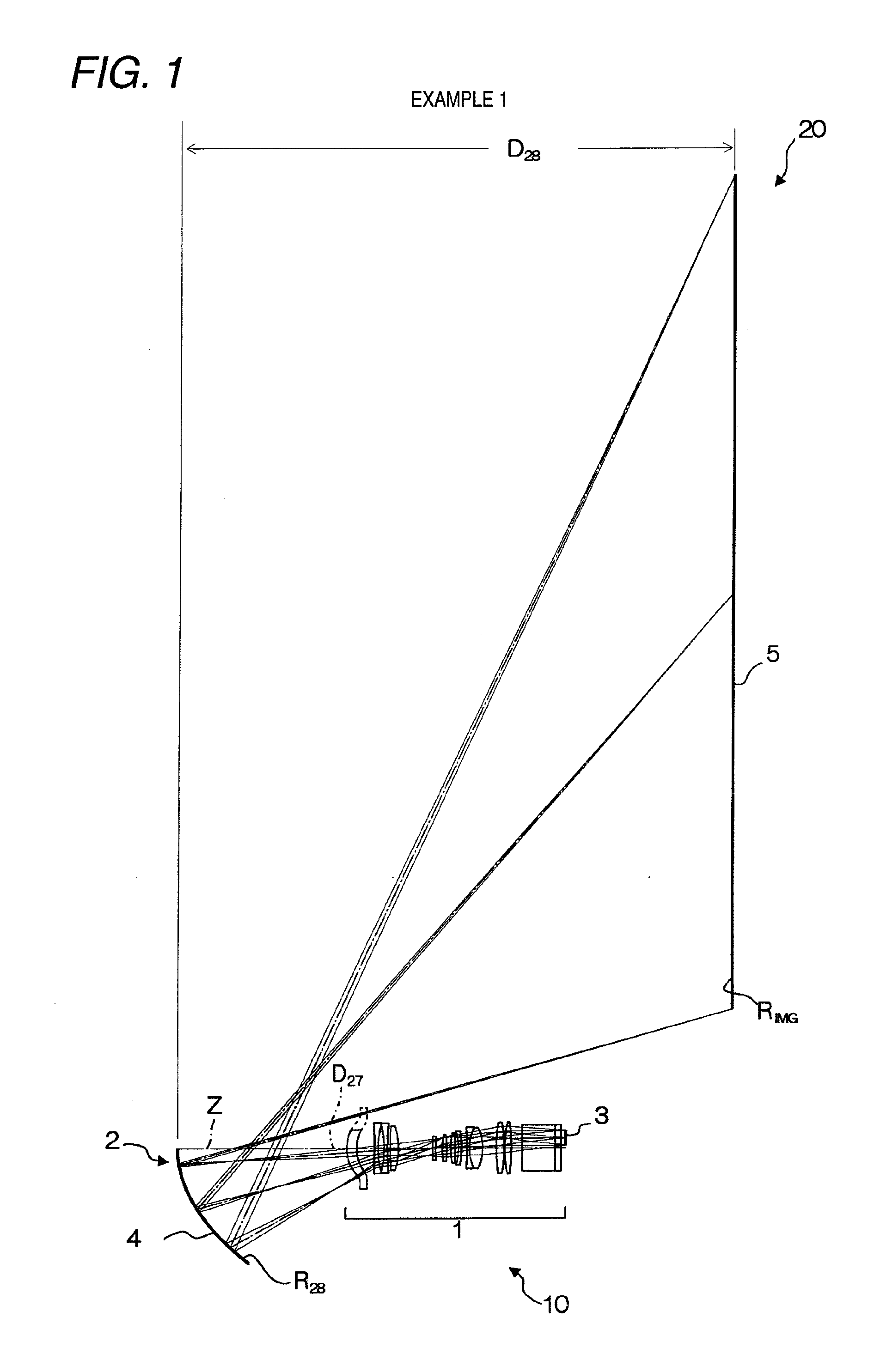
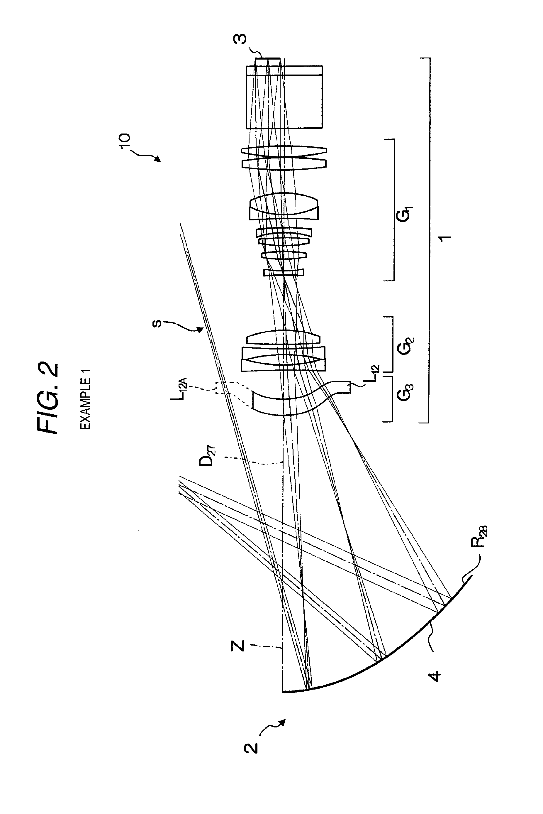
[0068]The structure of the projection type display 20 according to the first example is as shown in FIG. 1. The structure of the projection optical system 10 is as shown in FIG. 2. The detailed structure of the lens system constituting the first optical system 1 thereof is as shown in FIG. 3.
[0069]As shown in FIGS. 2 and 3, the first optical system 1 emits a luminous flux carrying image information which luminous flux is emitted from the image display device 3 disposed on the side above the optical axis Z in the figure, toward the reflecting mirror 4 included in the optical system 2 on the reduction side. The first optical system 1 is a so-called off-axial optical system, and includes in order from the object side: a cover glass (plane-parallel plate) 6, a prism section 7, a positive first lens group G1 including eight lenses L1 to L8; an aperture diaphragm 8; a second lens group G2 including three lenses L9 to L11; and a third lens group G3 (slightly negative near the optical axis)...
second embodiment
[0077]The structure of the projection type display 20 according to the second example is as shown in FIG. 5. The structure of the projection optical system 10 is as shown in FIG. 6. The detailed structure of the lens system constituting the first optical system 1 thereof is as shown in FIG. 7.
[0078]While the projection type display 20 and the projection optical system 10 according to the present example are structured substantially similarly to the projection type display 20 and the projection optical system 10 according to the first example as shown in FIGS. 6 and 7, they are different, particularly, in that the first lens group G1 includes seven lenses L1 to L7. The second lens group G2 includes three lenses L8 to L10, and the third lens group G3 includes one aspheric lens L11 that is slightly positive near the optical axis.
[0079]A rotationally asymmetric shape is adopted where the part L11A is missing that is outside the effective area of the lens L11 and interferes with the ligh...
PUM
 Abstract
Description
Claims
Application Information
 - R&D
- Intellectual Property
- Life Sciences
- Materials
- Tech Scout
- Unparalleled Data Quality
- Higher Quality Content
- 60% Fewer Hallucinations
Browse by: Latest US Patents, China's latest patents, Technical Efficacy Thesaurus, Application Domain, Technology Topic, Popular Technical Reports.
© 2025 PatSnap. All rights reserved.Legal|Privacy policy|Modern Slavery Act Transparency Statement|Sitemap|About US| Contact US: help@patsnap.com


