
Method and endoscopic device for examining or imaging an interior surface of a corporeal cavity

Inactive Publication Date: 2011-11-24
NANAMED
View PDF8 Cites 109 Cited by
  • Summary
  • Abstract
  • Description
  • Claims
  • Application Information

AI Technical Summary

Benefits of technology

[0036]In another embodiment of the invention, the auxiliary endoscopic imaging catheter is covered with a protective sheath, optionally disposable. Such a sheath, which is optionally made from a relatively inexpensive, transparent material such as polyethylene terephthalate (PET) or polycarbonate, allows using the endoscopic imaging catheter in multiple procedures, with multiple patients, without having to perform time consuming disinfective reprocessing procedures. Such a sheath may reduce the price of each one of the procedures. Optionally, such a sheath is designed for a single use to reduce the risk of patient to patient cross contamination. For example, the sheath may tear when removed or may be elastic and provided in everted form or rolled-up for mounting on the imaging catheter.
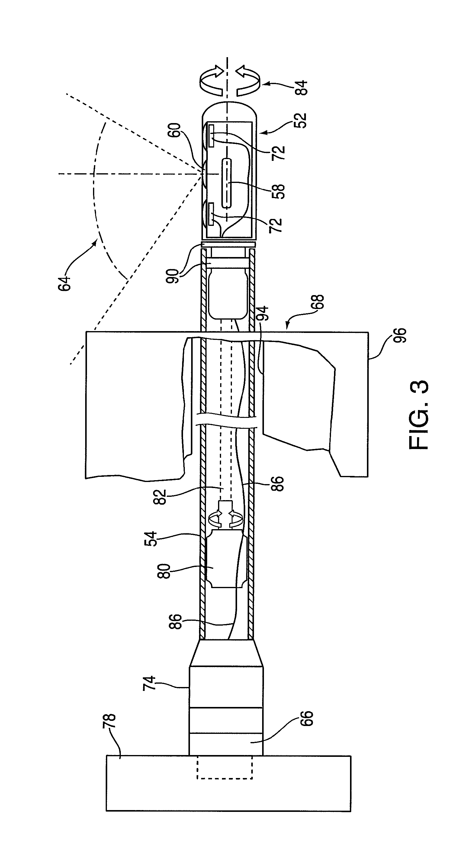
[0039]In other embodiments of the invention, the imaging element is distal to the mirror. In other embodiments the mirror is distal to the imaging elements. Optionally, the catheter is designed so that a line of sight of the imaging system of the imaging catheter exits near a distal end of the catheter. Optionally, this allows more distal imaging without over advancing of the imaging catheter. Optionally or alternatively, positioning of a mirror distally to the imaging element avoids a need to traverse the mirror with wires (if any) that connect the imaging element to the outside of the body.

Problems solved by technology

All these maneuvers of the endoscope prolong the procedure and cause added discomfort, complications, and risks to the patient.
The inability to view behind the tissue folds, flexures, and other “hidden” areas may cause a potentially polyp to be missed during a colonoscopy.

Method used


Image

  • Method and endoscopic device for examining or imaging an interior surface of a corporeal cavity
  • Method and endoscopic device for examining or imaging an interior surface of a corporeal cavity
  • Method and endoscopic device for examining or imaging an interior surface of a corporeal cavity

Examples


Embodiment Construction

[0046]Some embodiments of the invention are herein described, by way of example only, with reference to the accompanying drawings. With specific reference now to the drawings in detail, it is stressed that the particulars shown are by way of example and for purposes of illustrative discussion of embodiments of the invention. In this regard, the description taken with the drawings makes apparent to those skilled in the art how embodiments of the invention may be practiced.

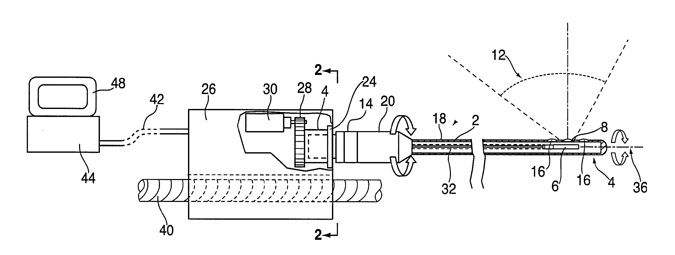
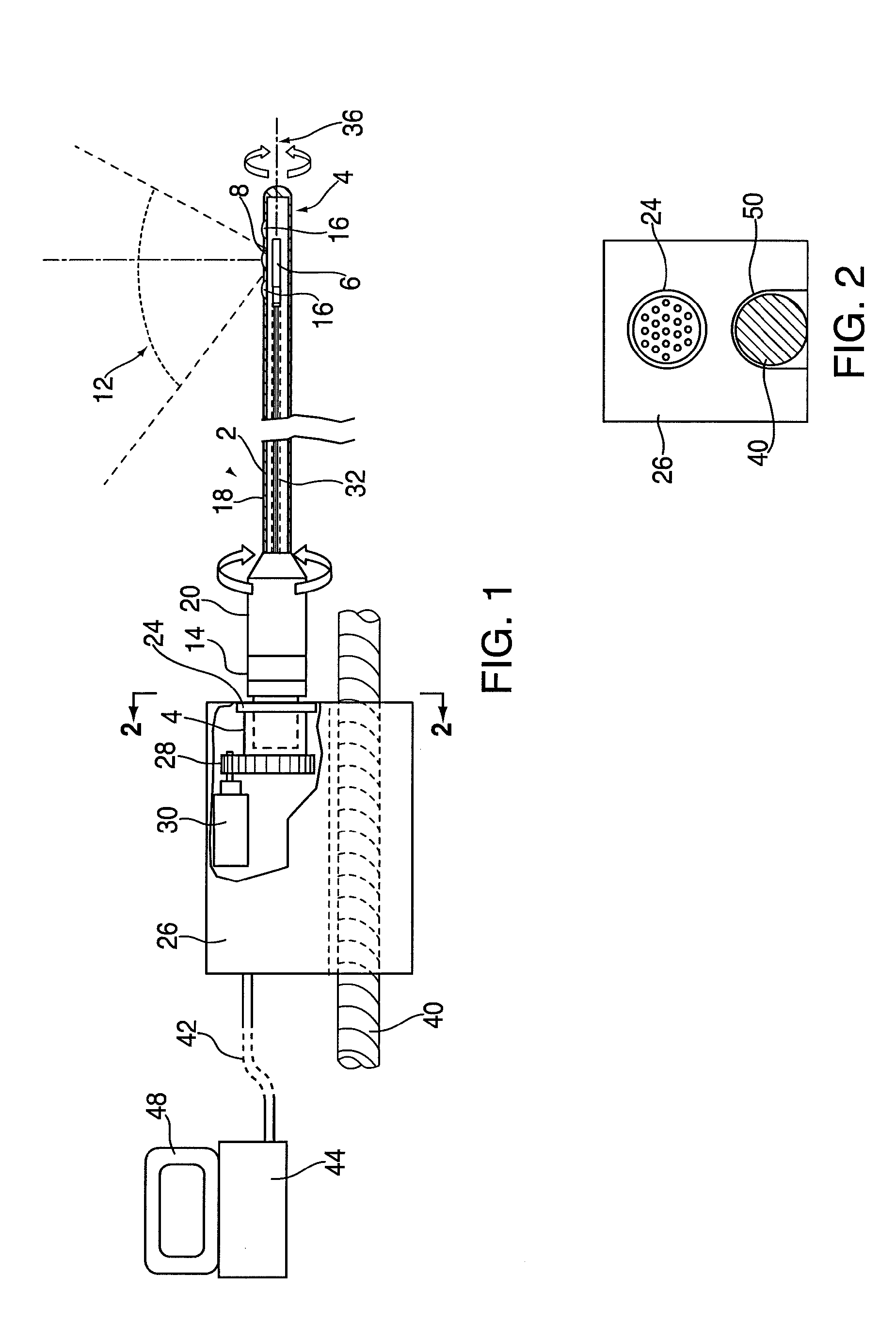
[0047]FIG. 1 shows a perspective view of an auxiliary endoscopic imaging catheter system according to one embodiment of the present invention. In this figure the entire auxiliary endoscopic catheter 2 rotates and / or wobbles. Catheter 2 comprises a sealed capsule 4 that comprises a camera 6 and side optical windows 8, which comprise a ring-like shape through the entire circumference of the capsule. Camera 6 is comprised of a single or multiple imaging sensor(s) (as CMOS or CCD) with its electronics as well as certain...


PUM


Abstract

An endoscopic imaging catheter is configured for insertion via a longitudinal channel of an endoscopic. The endoscopic imaging catheter includes an optical element, an imaging element, and a rotatable tubular shaft comprises an optical element and an imaging element, which comprise a side-looking imaging component. An endoscopic imaging catheter may alternatively comprise reflecting and optical elements and an imaging element. The reflecting element reflects onto the imaging element through the optical element side and rear views of at least a portion, or the entire 360° view of a wall encircling an intrabody lumen around the axis of said the longitudinal channel.

Description

CROSS-REFERENCE TO RELATED APPLICATION[0001]This application is based upon and claims the benefit of the filing date of co-pending, commonly assigned U.S. Provisional Patent Application Ser. No. 61 / 333,214, filed May 10, 2010, incorporated herein by reference.FIELD OF THE INVENTION[0002]The present invention relates to an endoscope assembly. More particularly, the invention relates to an endoscopic imaging catheter and a method of performing a medical procedure.BACKGROUND OF THE INVENTION[0003]An endoscope is a medical or industrial device comprising a flexible or rigid tube and a camera or fiber optics mounted on the distal end of the tube. The endoscope is insertable into an internal body cavity through a body orifice or a surgical incision to examine the body cavity and tissues as part of a diagnosis or therapeutic procedure. The tube of the endoscope has one or more longitudinal channels, which may be used for irrigation or suction, or through which an instrument can reach the b...

Claims


Application Information

Patent Timeline
IPC IPC(8): A61B1/06
CPCA61B1/00177A61B1/00172
Inventor HADANI, RONHARAMATY, LIOR
Owner NANAMED
Learn More