
Systems and methods for tissue ablation

a tissue ablation and system technology, applied in the field of thermal ablation systems and methods, to achieve the effect of facilitating procedures and inhibiting the ability of nerves

Inactive Publication Date: 2011-11-24
NIMBUS CONCEPTS
View PDF17 Cites 27 Cited by
  • Summary
  • Abstract
  • Description
  • Claims
  • Application Information

AI Technical Summary

Benefits of technology

[0029]For purposes of summarizing the invention and the advantages achieved over the prior art, certain objects and advantages of the invention are described herein. Of course, it is to be understood that not necessarily all such objects or advantages need to be achieved in accordance with any particular embodiment. Thus, for example, those skilled in the art will recognize that the invention may be embodied or carried out in a manner that achieves or optimizes one advantage or group of advantages as taught or suggested herein without necessarily achieving other objects or advantages as may be taught or suggested herein.

Problems solved by technology

A significant challenge in ablation therapy is to provide adequate treatment to the targeted tissue while sparing the surrounding structures from injury.

Method used


Image

  • Systems and methods for tissue ablation
  • Systems and methods for tissue ablation
  • Systems and methods for tissue ablation

Examples


example 1

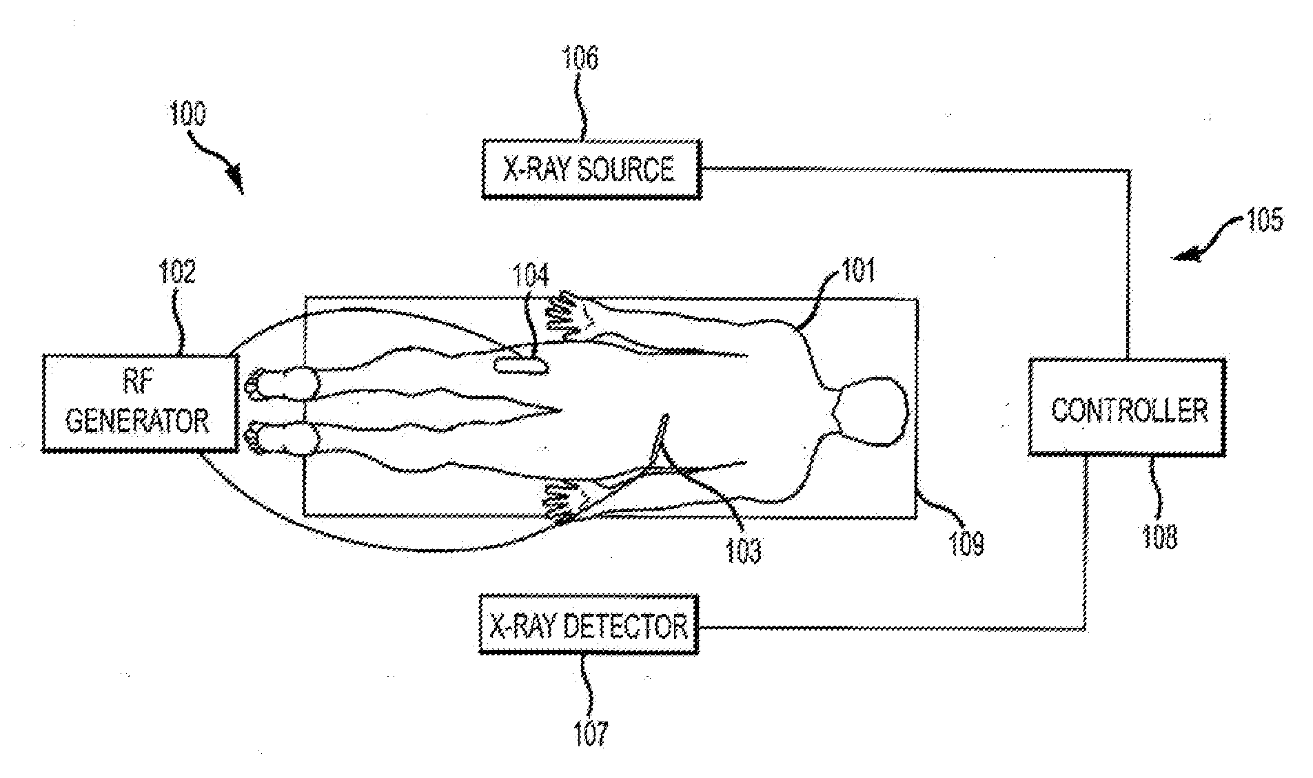
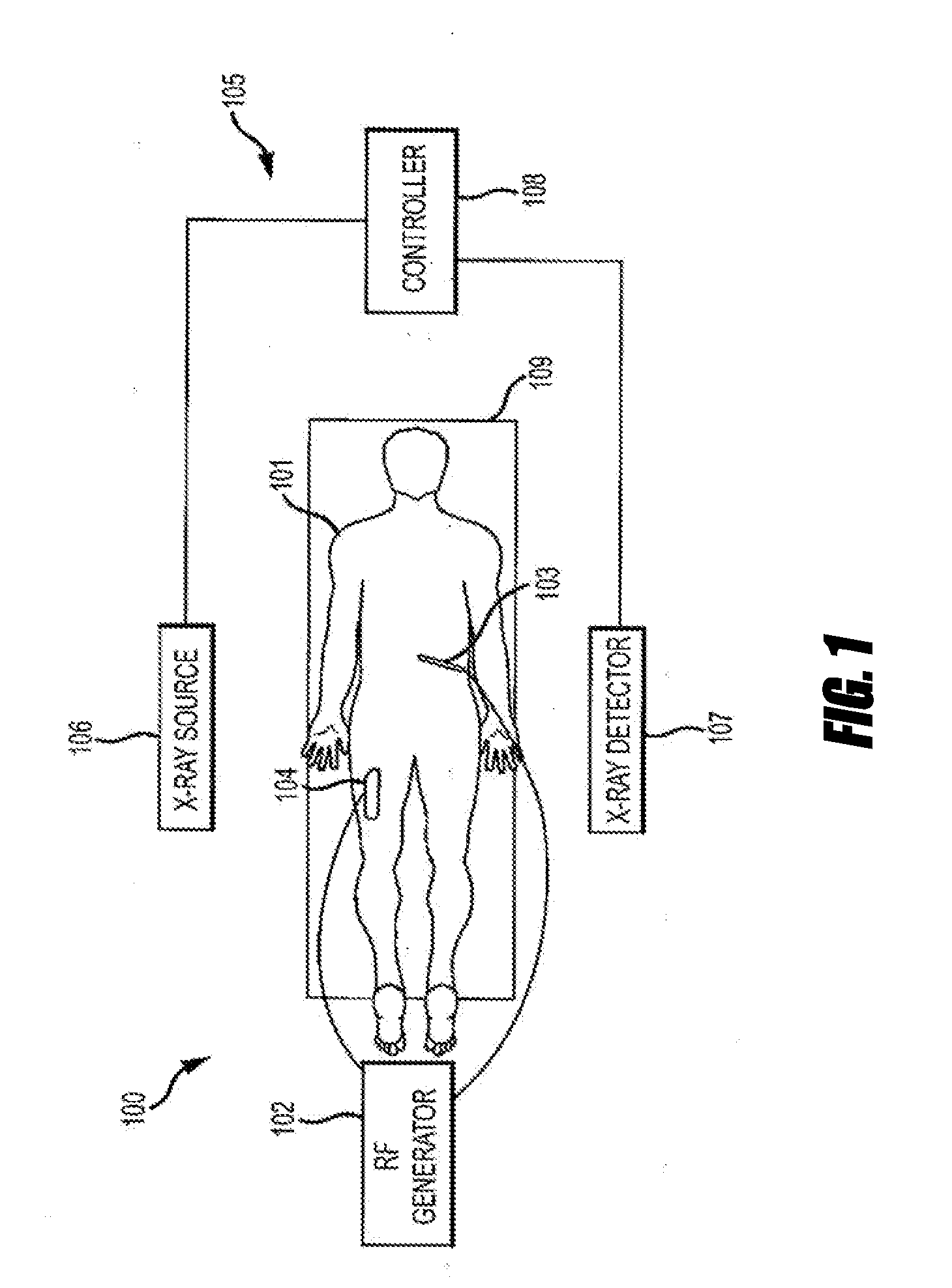
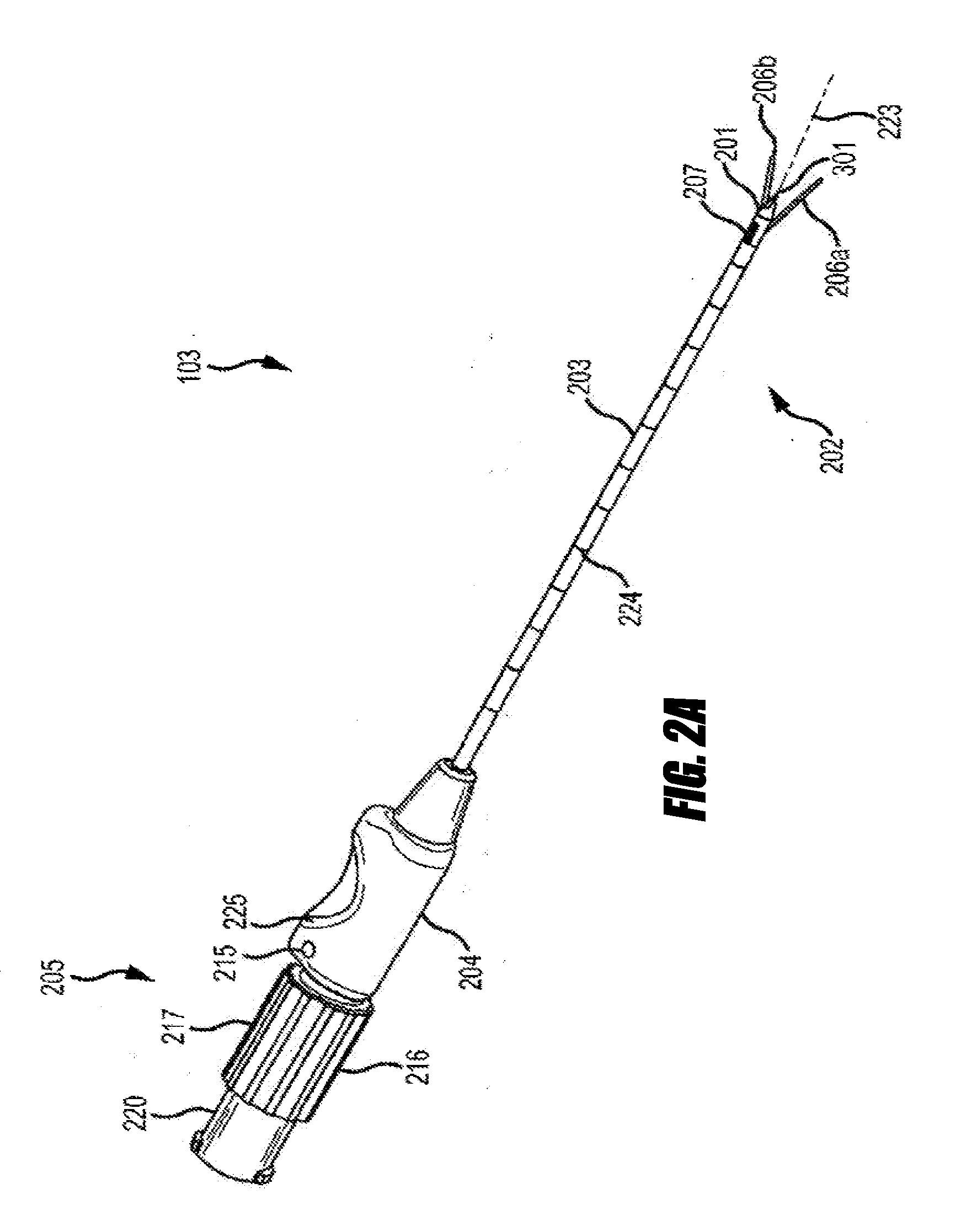
[0242]Sections of raw muscle tissue were allowed to equilibrate to 37° C. in a distilled water bath. A needle with tines deployed was positioned to contact the tissue surface in 10 trials and was inserted into tissue in 10 trials. A Radionics RFG 3C RF generator energy source was set at 75° C. for 80 seconds. Propagation of tissue coagulation was documented with video and a calibrated Flir T-400 thermal camera. Tissue samples were sectioned and coagulation zones measured. Infrared observation demonstrated symmetric and homogenous lesion progression without hot spots or focal over-impeding. Calculated volume averaged 467±71 mm3 / lesion. Topography was elongate spheroid offset from the central axis toward the filaments. Thus, the needle reliably produced lesions that are potentially useful in spinal applications.

example 2

[0243]A 47 year-old male with recalcitrant right-sided lumbar zygapophysial joint pain presented for radiofrequency medial branch neurotomy. The diagnosis had been made by greater than 80% relief documented following both intraarticular z-joint injection and confirmatory medial branch blocks.

[0244]The patient was placed in a prone position on the fluoroscopy table and standard monitors were applied. No sedation was administered. The lumbar region was extensively prepped with chlorhexidine-alcohol and draped in routine sterile surgical fashion. The C-arm was adjusted to visualize a true AP of the L4 / 5 intervertebral disc space with vertebral end plates squared-off, and spinous process positioned between the pedicle shadows. The C-arm was rotated 30°-40° ipsilateral to the target joint until the base of the SAP of the L4 and L5 were clearly visualized, A target point was identified at the midpoint of the base of the SAP, and the overlying skin and subcutaneous tissues were infiltrated...


PUM


Abstract

Systems and methods for tissue ablation. Systems include needles with deployable filaments capable of producing asymmetrical offset lesions at target volumes, which may include a target nerve. Ablation of at least a portion of the target nerve may inhibit the ability of the nerve to transmit signals, such as pain signals, to the central nervous system. The offset lesion may facilitate procedures by directing energy towards the target nerve and away from collateral structures. Example anatomical structures include lumbar, thoracic, and cervical medial branch nerves and rami and the sacroiliac joint.

Description

CROSS-REFERENCE TO RELATED APPLICATIONS[0001]This application claims priority benefit under 35 U.S.C. §119(e) of U.S. Provisional Patent Application No. 61 / 347,351, filed May 21, 2010, U.S. Provisional Patent Application No. 61 / 357,886, filed Jun. 23, 2010, and U.S. Provisional Patent Application No. 61 / 357,894, filed Jun. 23, 2010, each of which is incorporated herein by reference in its entirety.BACKGROUND[0002]1. Field[0003]The present application generally relates to thermal ablation systems and methods, and more particularly to systems and methods for radio frequency (RF) neurotomy, such as spinal RF neurotomy.[0004]2. Description of the Related Art[0005]Thermal ablation involves the creation of temperature changes sufficient to produce necrosis in a specific volume of tissue within a patient. The target volume may be, for example, a nerve or a tumor. A significant challenge in ablation therapy is to provide adequate treatment to the targeted tissue while sparing the surroundin...

Claims


Application Information

Patent Timeline
Patent Type & Authority Applications(United States)
IPC IPC(8): A61B18/18
CPCA61B18/1477A61B2018/0044A61B2018/1475A61B2018/143A61B2018/1427A61B18/1206A61B2018/1253A61B2018/00577
Inventor WRIGHT, ROBERT E.BRANDT, SCOTT A.
Owner NIMBUS CONCEPTS
Learn More