Ultrasonic Sensor

a technology of ultrasonic sensors and sensors, applied in the direction of mechanical vibration separation, instruments, pedestrian/occupant safety arrangements, etc., can solve the problems of increasing the reverberation time, not all the vibration transmitted from the side wall of the case toward the filler can be absorbed, and the reverberation characteristics are improved. , the effect of short-range detection

Active Publication Date: 2011-12-01
MURATA MFG CO LTD
View PDF13 Cites 15 Cited by
  • Summary
  • Abstract
  • Description
  • Claims
  • Application Information

AI Technical Summary

Benefits of technology

[0012]Accordingly, it is an object of the present invention to provide an ultrasonic sensor capable of improving b

Problems solved by technology

However, such an ultrasonic sensor having a pin terminal structure in which a pin protrudes from a case has two major drawbacks described below.
However, if the inside is filled with a filler having a high modulus of elasticity, not all vibration transmitted from the side wall of the case toward the filler can be absorbed by the filler, and the vibration is transmitted to the pin terminal.
The leakage of the vibration through the terminal is hereinafter referred to simply as “vibration leakage.” If there is vibration leakage, an unnecessary signal component (p

Method used


Image

  • Ultrasonic Sensor
  • Ultrasonic Sensor
  • Ultrasonic Sensor

Examples


first embodiment

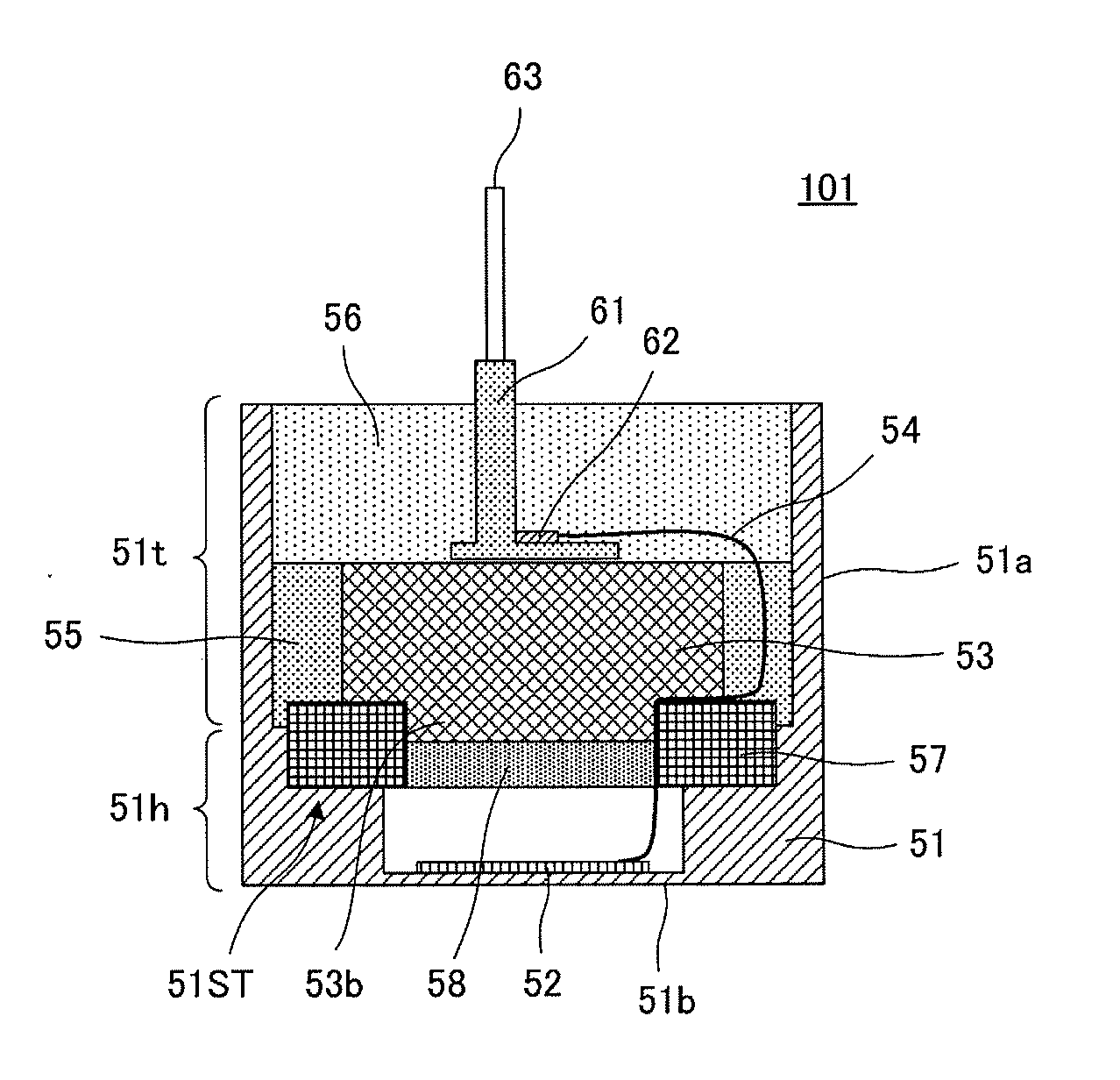
[0031]FIG. 4 is a cross-sectional view of an ultrasonic sensor 101 according to a first embodiment. The ultrasonic sensor 101 includes a substantially cylindrical case 51 including a bottom portion 51b and a side wall portion 51a and a plurality of members disposed in this case 51. The case 51 can be an aluminum compact, for example. The side wall portion 51a includes a thin section 51t at its opening side and a thick section 51h at its bottom side. The bottom portion 51b has a hollow having the shape of a substantially oval with long and short axes. Both ends of the hollow in the short-axis direction are the thin section 51h.

[0032]Reinforcement (weight) 57 having a substantially ring shape is fitted on the thick section 51h in the case 51 at a location that is not in contact with an inner surface of the thin section 51t of the side wall portion 51a. The reinforcement (weight) 57 can be a member that has higher acoustic impedance than that of the case 51. For example, the reinforce...

second embodiment

[0040]FIG. 6 is cross-sectional view of an ultrasonic sensor 102 according to a second embodiment. For the ultrasonic sensor 102, the elastic member 53 has a recess in the upper surface, and the terminal holding member 61 is arranged in the recess. The bottom of the terminal holding member 61 is at a deep location within the case 51. Therefore, the terminal holding member 61 in the ultrasonic sensor 102 is longer than that illustrated in FIG. 4. The other configuration is substantially the same as in the ultrasonic sensor 101 illustrated in the first embodiment.

[0041]With the structure illustrated in FIG. 6, the terminal holding member 61 is in contact with the second filler 56 over a long distance, and this second filler 56 virtually prevents propagation of vibration from the side wall portion 51a of the case 51 to the terminal holding member 61 and its inner pins. Therefore, no vibration leakage occurs, and durability to withstand undesired pullout or separation of the terminal ho...

third embodiment

[0042]FIG. 7 is a cross-sectional view of an ultrasonic sensor 103 according to a third embodiment. For the ultrasonic sensor 103, the first filler 55 in the case 51 extends over the entire inner surface of the thin section 51t of the side wall portion 51a of the case 51. The gap between the first filler 55 and the terminal holding member 61 is filled with the second filler 56. The other configuration is substantially the same as in the ultrasonic sensor 101 illustrated in the first embodiment.

[0043]With the structure illustrated in FIG. 7, because the first filler 55 is in contact with the wide range of the side wall portion 51a of the case 51, the ultrasonic sensor can achieve more satisfactory reverberation characteristics.


PUM


Abstract

An ultrasonic sensor includes a substantially cylindrical case including a bottom portion and a side wall portion and a plurality of members disposed within the case. A reinforcement having a substantially ring shape is fitted on a thick section in the case at a location that is not in contact with an inner surface of a thin section of the side wall portion. A piezoelectric element is attached to an inner bottom surface of the case. An elastic member is fitted on the reinforcement so as to cover a substantially ring-shaped opening region of the reinforcement. A gap between the elastic member and an inner circumferential surface of the case is filled with a first filler. The terminal holding member is placed on the elastic member. A surrounding region of the terminal holding member is filled with a second filler.

Description

BACKGROUND OF THE INVENTION[0001]1. Field of the Invention[0002]The present invention relates to ultrasonic sensors and, in particular, an ultrasonic sensor that includes a piezoelectric element and an input / output terminal electrically coupled thereto and that can be used in automotive corner sonar or back sonar, for example.[0003]2. Description of the Related Art[0004]An ultrasonic sensor uses ultrasonic waves in sensing and detects an object by intermittently transmitting an ultrasonic pulse signal and receiving a reflected wave from the obstacle present in neighboring areas. An ultrasonic sensor can be employed in automotive back sonar, corner sonar and, additionally, a parking sensor for detecting the presence of a space to an obstacle, such as a side wall, in parallel parking.[0005]An example of this type of ultrasonic sensor is described in Japanese Unexamined Patent Application Publication No. 2000-32594. FIG. 1 is a cross-sectional view of an ultrasonic sensor 30 illustrate...

Claims


Application Information

Patent Timeline
IPC IPC(8): G10K11/16H01L41/053
CPCG10K11/002G10K9/122H04R17/00B60R21/00G01S7/521B06B1/0644B06B1/0685
Inventor SATO, TAKEHIRO
Owner MURATA MFG CO LTD
Why Eureka
Try Eureka