Boat hull strake design

Inactive Publication Date: 2011-12-08
QUIMBY JOHN I
View PDF4 Cites 4 Cited by
  • Summary
  • Abstract
  • Description
  • Claims
  • Application Information

AI Technical Summary

Benefits of technology

[0002]The inventive use of attachable strakes, or designed into the hull, forces the normally outward flowing water back under the hull and this forced redirection of the water back under the hull, a massive bed of foam bubbles is created resulting in reducing the original planning surface friction to a minimum. This inventive concept uses strakes which are designed to put the largest possible amount of air containing bubbles under the largest amount of the otherwise planning

Problems solved by technology

Some of them extend too close to the bow of small boats and in rough water can

Method used


Image

  • Boat hull strake design
  • Boat hull strake design
  • Boat hull strake design

Examples


Example

[0016]FIGS. 1A-1C illustrate a conventional design of a boat showing The bottom of a boat, a rear view and a side view.

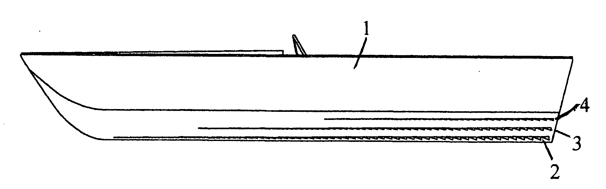
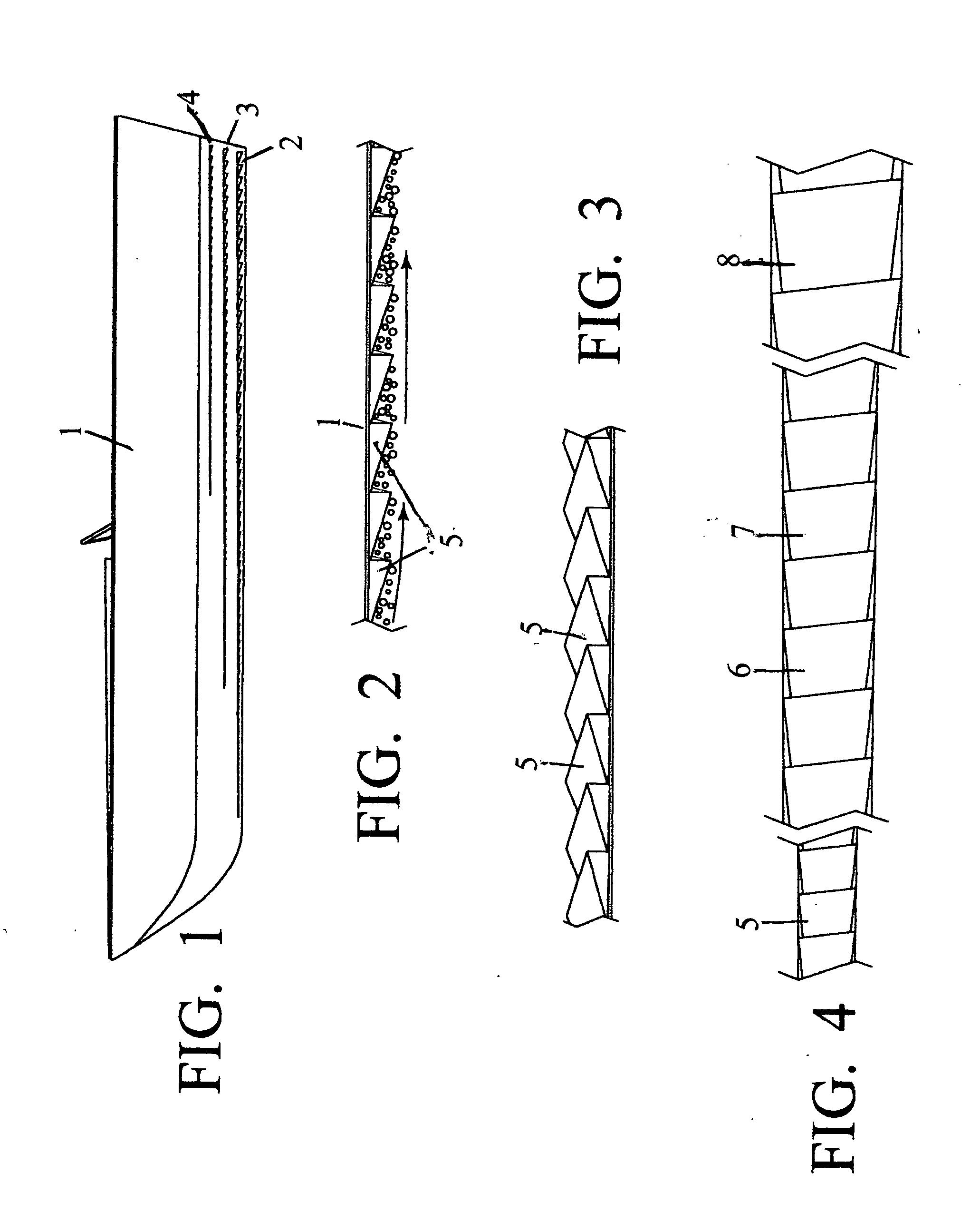
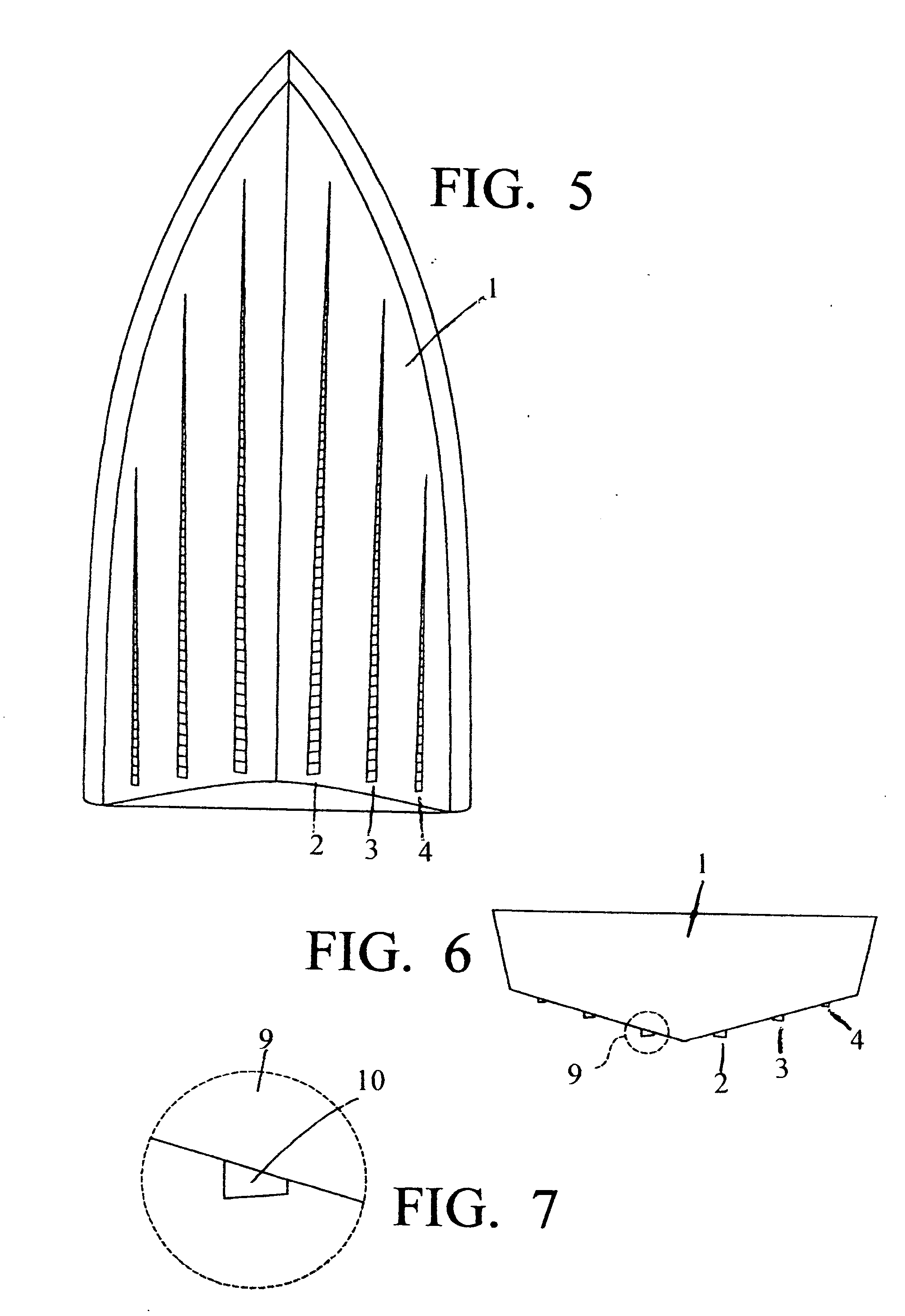
[0017]FIG. 1 illustrates a side view of a boat having several strakes attached to the bottom from the keel shown at 2, the side of the boat hull 3 and further up the side shown at 4. These strake series are space apart from each in a horizontal manner and they can be of different lengths.

[0018]FIG. 2 shows how the individual strakes 5 create a a stream of bubbles 5. The individual strakes are slanted upwardly as seen from the direction of the travel of the boat. This slant is especially constructed because , once the water flow passes over the strakes, it creates somewhat of a venturi effect which aids in the creation of the bubbles which is the basic aim of the inventive concept.

[0019]FIG. 3 is a perspective view of a line of strakes where the slant of the individual strakes can be observed. The individual strakes are also canted relative to the hull of the boat or...


PUM


Abstract

A system for increasing the buoyancy of a boat operating in the water and to reduce the wetted-surface-friction of the water against the hull of the boat. The system includes a multiple of strakes attached to the bottom side of the boat. The strakes are instrumental in creating a multitude of bubbles on which the hull of the boat will ride which increases the efficiency of the power of the motor or motors powering the boat. The strakes are arranged in series along the hull of the boat and can increase in size from the bow of the boat to the stern. The strakes are also increasing in depth from the bow of the boat to the stern. The strakes may be attached to the boat as a retro-fit or may be added when manufacturing the boat.

Description

BACKGROUND OF THE INVENTION[0001]Designers and manufactures of planning boat hulls have for years used a variety of means to attempt to have the least amount of solid water in contact with the hull of a boat when planning on the hull surface. Probably the earliest designs for hulls on boats without the usual framing, utilizing overlapping planking, which is known as “Lapstrake” or “Clinker” style hulls, which were originally created by the Vikings. This construction method of the overlapping planking was applied by some early wooden boat builders to eliminate conventional framing and also reduce the weight for planning hulls, which incidentally created some bubbles for probably the very first time, which reduced some of the ordinary water-to hull friction from solid water under the hull. Others have tried cross-wise steps in their hulls to draw air under the hull and create bubbles to reduce friction. Still others have tried length-wise air tunnels and some bubble creation, again to...

Claims


Application Information

Patent Timeline
IPC IPC(8): B63B1/38
CPCY02T70/122B63B1/38Y02T70/10
Inventor QUIMBY, JOHN I.
Owner QUIMBY JOHN I
Why Eureka
Try Eureka