Magnet unit and magnetron sputtering apparatus

a magnet unit and sputtering technology, applied in the direction of magnets, magnet bodies, vacuum evaporation coatings, etc., can solve the problems of difficult to project an erosion point, uneven erosion, and eroded target surface with elapsed operation time, so as to prolong the target life and reduce the parallel rotation of the magnet unit. , the effect of reducing the magnetic track region

Active Publication Date: 2011-12-08
CANON ANELVA CORP
View PDF5 Cites 5 Cited by
  • Summary
  • Abstract
  • Description
  • Claims
  • Application Information

AI Technical Summary

Benefits of technology

[0019]According to the magnet unit of this invention, the magnetic track regions parallel to the rotation direction of the magnet unit is reduced greatly and the magnetic tracks perpendicularly crossing the rotation direction of the magnet unit are increased, and thereby it becomes possible to cause the erosion occurring on the target to progress without being concentrated on a specific region and to extend the target life.

Problems solved by technology

Meanwhile, the ion flicks an element on the target surface and thereby the target surface is eroded along with the elapse of operation time.
However, it is difficult to project an erosion point and the erosion speed at the time of magnetic circuit design performed only by way of such a geometric shape.
However, Japanese Patent Application Laid-Open Publication No. 2009-7637 does not explain to the point whether the magnetic flux density is uniform or not on the magnetic track, and the erosion does not always progress uniformly there.
In particular, when the target is made of magnetic material, most of the magnetic force lines from the cathode magnet pass through the inside of the target, and thereby it is difficult to generate the magnetic track on a magnetic circuit in the same manner as in the design shown in FIG. 24A.
That is, there is a limitation for a method in which the magnetic track includes many regions parallel to the rotation direction of the magnet unit and radii are shifted from one another in the convex and concave parts of the magnetic tracks, as the method of Japanese Patent Application Laid-Open Publication No. 2009-7637.
In particular, when the target diameter is increased, it is difficult to cause the erosion to progress uniformly across the whole surface of the target without providing many radii for the convex parts and concave parts of the magnetic track.

Method used


Image

  • Magnet unit and magnetron sputtering apparatus
  • Magnet unit and magnetron sputtering apparatus
  • Magnet unit and magnetron sputtering apparatus

Examples


example 1

[0084]Regarding the mode shown in FIG. 10 to which an embodiment of the present invention can be applied, the shape of the magnetic track and the magnetic flux density were confirmed and also the erosion shape was confirmed. The yoke 712 including iron as a main component (Japanese Industrial Standards SS400) has a diameter of 370 mm and a thickness of 10 mm. The magnet element 7011, which has a length of 100 mm, a width of 70 mm, and a height of 37 mm, the magnet element 7012, which has a length of 150 mm, a width of 40 mm, and a height of 37 mm, and the magnet element 7013, which has a length of 150 mm, a width of 40 mm, and a height of 37 mm, are fixed onto the yoke 712 with epoxy series adhesive for constituting the internal magnet 701. The outer surface of the internal magnet unit 701 is assumed to have the S-pole (i.e., adhesion surface of the yoke 712 has the N-pole). The external magnet unit 702 (outer surface has the N-pole) is fixed onto the yoke 712 with the epoxy series ...

example 2

[0088]This time, a magnetic target 1502 of iron-cobalt alloy (saturation magnetic flux density: 2.4 T) is disposed close to the magnet unit shown in Example 1 and the magnetic track shape and the magnetic flux density were confirmed and also the eroded shape was confirmed on the magnetic target 1502. Here, the target has a diameter of 380 mm and a thickness of 3 mm, and the distance between the surface of the magnet unit and the surface of the magnetic target 1502 is 16 mm.

[0089]At this time, the magnetic track shape appearing on the magnetic target 1502 was confirmed and a result was obtained as shown in FIG. 14. Further, a region, where a magnetic field component parallel to the surface of the magnetic target 1502 was equal to larger than 50 mT, was obtained as shown in FIG. 15, and it was confirmed that a magnetic flux density enabling stable discharge was obtained also on the magnetic target in the magnet unit to which an embodiment of the present invention could be applied.

[009...

example 3

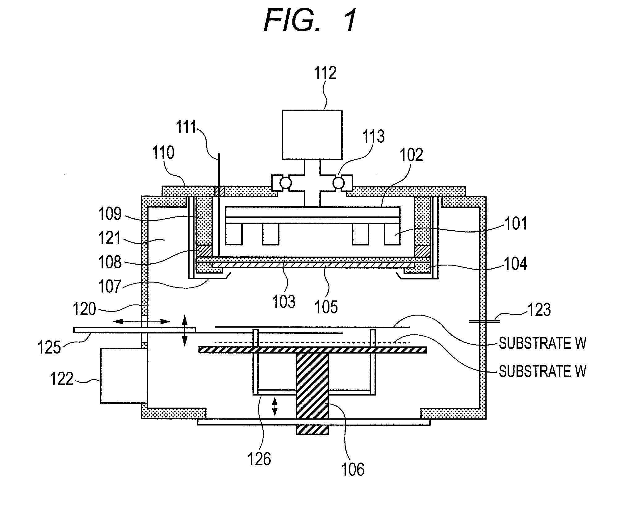
[0091]FIG. 17 shows a magnet unit of a seventh example which is a modification of the magnet unit of the first example shown in FIG. 2. The feature of the magnet unit of the seventh example shown in FIG. 17 is the following point. An internal magnet unit 401 (e.g., S-pole) includes three magnet elements 4011, 4012, and 4013 which extend radially in at least n-directions (n=3) from the radial center 4100 which coincides with the rotation center of the yoke. Meanwhile, an external magnet unit 402 (e.g., N-pole) has a (3n−1) or more-angular shape (3×3−1=8) which are arranged so as to surround the above three magnet elements 4011, 4012, and 4013 and includes (3n−1) external magnets (3×3−1=8) 4021 to 4028. In such a configuration, the above three magnet elements 4011, 4012, and 4013 are arranged in the circumferential direction having angles of 90 degrees, 90 degrees, and 180 degrees in between, respectively.

[0092]Note that, also in the magnet unit of the seventh example shown in FIG. 17...


PUM

PropertyMeasurementUnit
angleaaaaaaaaaa
angleaaaaaaaaaa
diameteraaaaaaaaaa

Abstract

The present invention provides a magnet unit and a magnetron sputtering apparatus which can suppress the consumption amount of a target by efficiently consuming the target and can easily cause erosion on the target to progress uniformly regardless whether the target size is small or large and whether the target is made of magnetic material or not. A magnet unit according to an embodiment of the present invention includes a member configured to be provided with a predetermined magnet, an internal magnet unit which is provided for the member and includes n magnet elements extending radially in the surface of the member from a predetermined position of the member in at least n (n: positive integer equal to or larger than 3) directions, the n magnet elements having one polarity on a side opposite to the member, and an external magnet unit which is provided for the member so as to surround the internal magnet unit along the shape of the internal magnet unit, the external magnet unit having the other polarity on a side opposite to the member.

Description

BACKGROUND OF THE INVENTION[0001]1. Field of the Invention[0002]The present invention relates to a magnet unit which is disposed on the backside of a cathode electrode supporting a target on the front side in sputtering and relates to a magnetron sputtering apparatus provided with the magnet unit.[0003]2. Description of the Related Art[0004]A magnetron sputtering apparatus generates magnetron on a target discharge surface using a magnet unit which is disposed on the back side of a cathode electrode supporting the target and confines the plasma to obtain a high density state thereof. Then, when an ion of the plasma generated in this apparatus collides with the target, target material is flicked out and attached to a substrate to form a thin film. The sputtering used in a deposition process of the semiconductor industry deposits a film from any kind of source material, and can deposit a high melting-point material such as platinum and tungsten and an insulating material, for example. ...

Claims


Application Information

Patent Timeline
Patent Type & Authority Applications(United States)
IPC IPC(8): C23C14/35H01F7/02
CPCH01J37/3452H01J37/3408
Inventor ENDO, TETSUYAABARRA, EINSTEIN NOEL
Owner CANON ANELVA CORP
Why Eureka
Try Eureka