X-ray waveguide

a waveguide and x-ray technology, applied in the field of x-ray waveguides, can solve the problems of increasing the propagation loss of x-ray, difficult to produce a core region, deterioration or structural change of the waveguide, etc., and achieves the effect of small propagation loss of an x-ray and easy production

Inactive Publication Date: 2011-12-08
CANON KK
View PDF0 Cites 9 Cited by
  • Summary
  • Abstract
  • Description
  • Claims
  • Application Information

AI Technical Summary

Benefits of technology

[0009]The present invention has been made in view of such conventional problems as described above, and an object of the present invention is to provide an X-ray waveguide which: shows a small propagation loss of an X-ray; does not deteriorate owing to oxidation; and can be easily produced.

Problems solved by technology

H03-146909, however, it is difficult to produce a core region having such a small diameter that an independent waveguide mode of an X-ray is formed or to uniformly form a laminated film of a cladding on the outer periphery of the fiber.
In addition, since an inorganic material that absorbs the X-ray to a large extent is used in the cladding, the propagation loss of the X-ray increases.
Further, the oxidation of the inorganic material may cause the deterioration or structural change of the waveguide.
In addition, a labor and time is required for the step of laminating those materials to show sufficient reflectance.

Method used


Image

  • X-ray waveguide
  • X-ray waveguide
  • X-ray waveguide

Examples


example 1

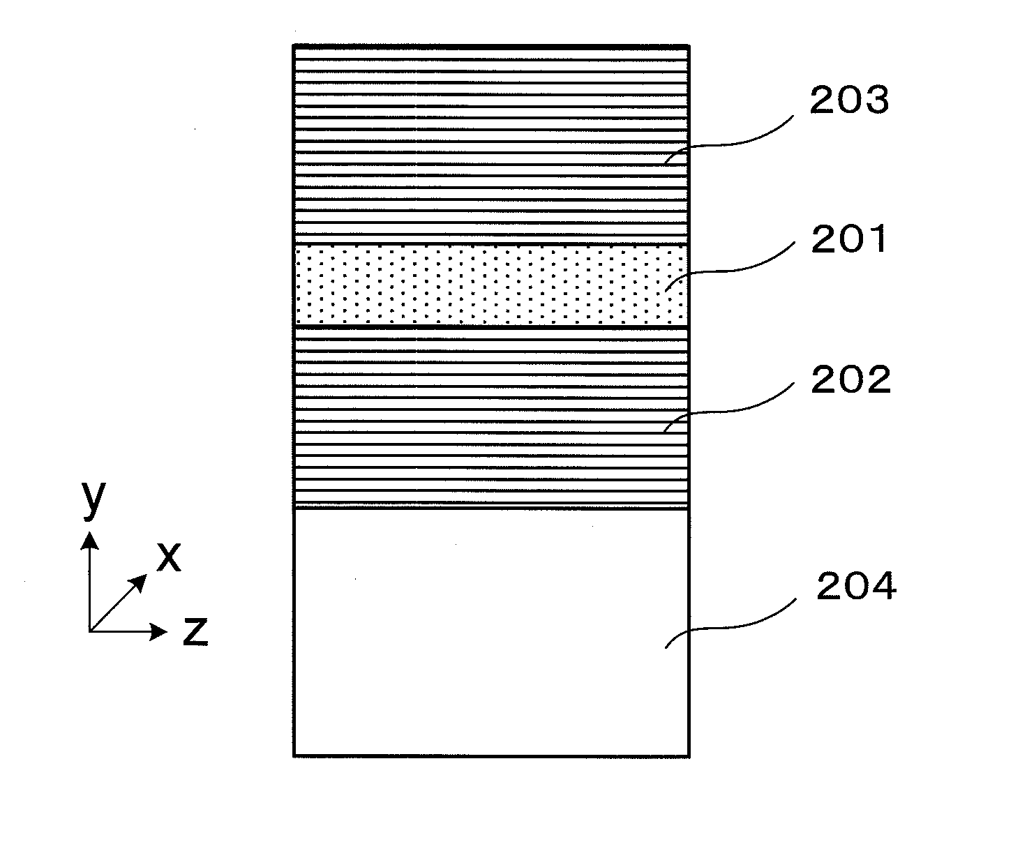
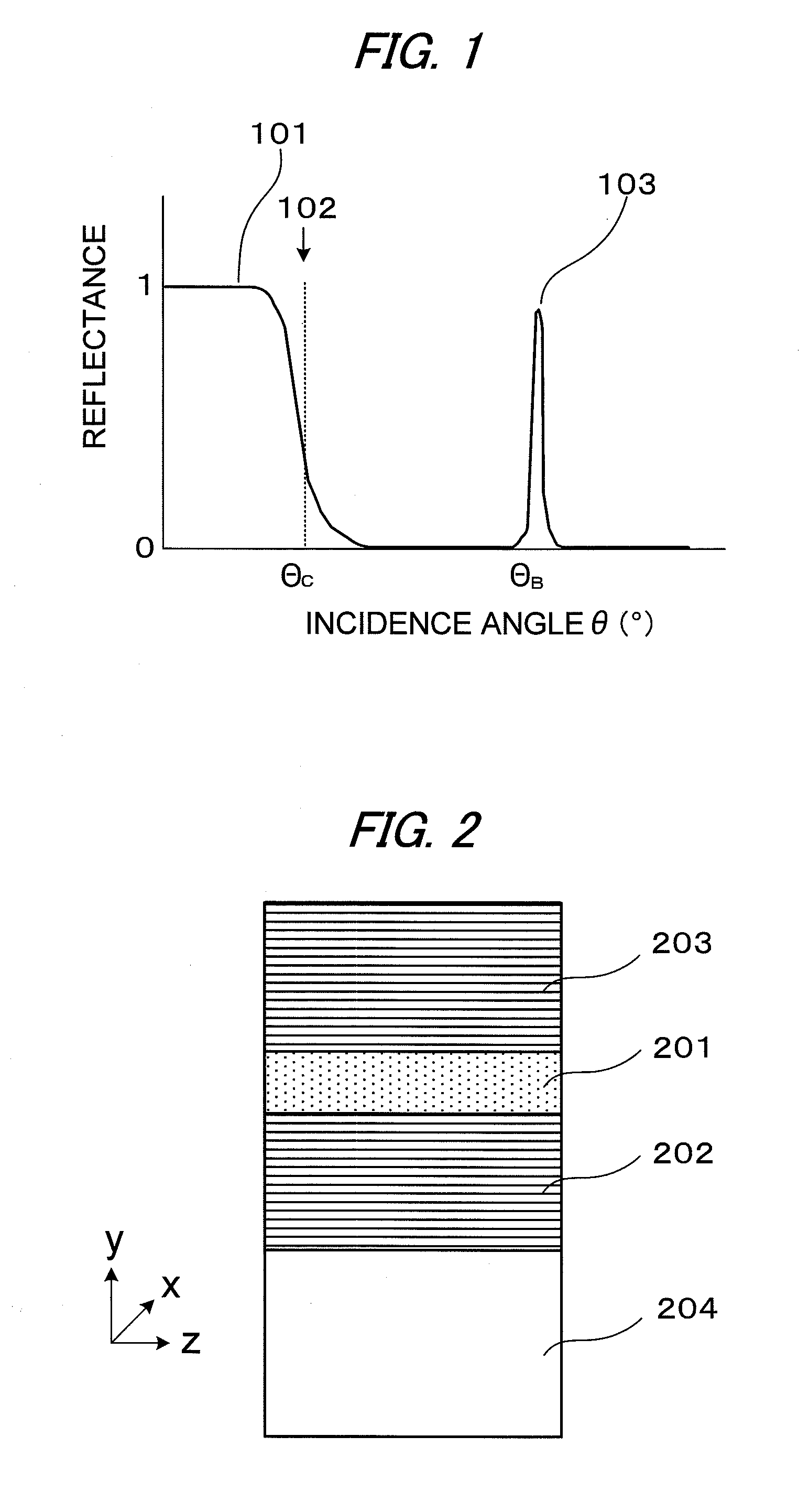
[0061]FIG. 2 is a view illustrating Example 1 of the X-ray waveguide of the present invention. A lamellar film 202 formed as a multilayer film to serve as a cladding is formed on an Si substrate 204. Then, PDMS having a thickness of about 32 nm is formed as a core 201 on the film by spin coating. Further, a lamellar film 203 is formed on the core. The inorganic material of the lamellar films is SiO2. The lamellar films 202 and 203 of this example are produced by the following method.

[0062](a) Preparation of Solution

[0063]A mesostructured film having a lamellar structure is prepared by a spin coating method. A precursor solution is prepared by dissolving n-decyltrimethoxysilane, tetramethoxysilane, water, and hydrochloric acid in a tetrahydrofuran solvent, and stirring the resultant at 25° C. for 3 hours. The mixing ratio (molar ratio) of n-decyltrimethoxysilane, tetramethoxysilane, water, hydrochloric acid, and tetrahydrofuran is set to 1:4:19:0.01:20.

[0064](b) Film Formation

[0065]A...

example 2

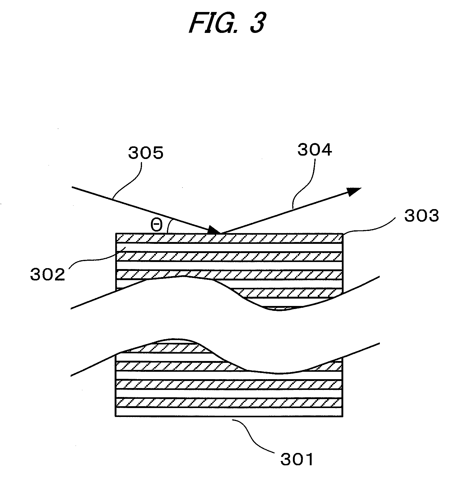
[0071]FIG. 4 is a view illustrating Example 2 of the X-ray waveguide of the present invention. The claddings of this example are the films of a mesoporous silica (mesoporous material) whose inorganic material is silica (SiO2), and the inside of each pore of the film is filled with air. The X-ray of waveguide mode propagates in a z direction in the figure. The X-ray waveguide of this example is such that the film of the mesoporous silica is formed as a cladding 402 or 403. However, a core 401 is formed of air. The mesoporous silica film is of a structure having a one-dimensional periodicity in a y direction in the figure, and the period of the structure is about 6 nm. A lamellar film is formed on each of Si substrates 404 and 405, and Au pattern of about 50 nm height is made on the surface of each Si substrates by sputtering, lithography, and etching process. After that, both the Si substrates are attached to each other so that the respective mesoporous silica films may be opposite t...


PUM


Abstract

An X-ray waveguide which: shows a small propagation loss of an X-ray; does not deteriorate owing to oxidation; and can be easily produced is realized with an X-ray waveguide, including: a core for guiding an X-ray in such a wavelength band that the real part of refractive index of materials is 1 or less; and a cladding for confining the X-ray in the core, in which: the cladding has a one-dimensional periodic structure consisting of at least two materials having different real parts of refractive index; one of the materials is inorganic one, and another one of materials is any of an organic material, a gas, or vacuum; and the core and the cladding are formed so that the critical angle for total reflection at the interface between the core and the cladding is smaller than a Bragg angle depending on the periodicity of the one-dimensional periodic structure.

Description

BACKGROUND OF THE INVENTION[0001]1. Field of the Invention[0002]The present invention relates to an X-ray waveguide, in particular, an X-ray waveguide used in an X-ray optical system, for example, in an X-ray analysis technology, an X-ray imaging technology, or an X-ray exposure technology.[0003]2. Description of the Related Art[0004]When an electromagnetic wave having a short wavelength of several tens of nanometers or less is dealt with, a difference in refractive index for any such electromagnetic wave between different materials is extremely small, specifically, 10−4 or less, and thus, for example, a critical angle for total reflection becomes extremely smaller. In view of the foregoing, a large-scale spatial optical system is usually used for controlling such an electromagnetic wave including an X-ray. Among the main components of which the spatial optical system is formed, multilayer mirrors obtained by alternately laminating materials having different refractive indices are p...

Claims


Application Information

Patent Timeline
Patent Type & Authority Applications(United States)
IPC IPC(8): G21K1/00
CPCB82Y10/00G21K2201/067G21K2201/061G21K1/062
Inventor OKAMOTO, KOHEIKOMOTO, ATSUSHIKUBO, WATARUMIYATA, HIROKATSUNOMA, TAKASHI
Owner CANON KK
Why Eureka
Try Eureka