Bi-fuel engine with variable air fuel ratio

a technology of air fuel ratio and bi-fuel engine, which is applied in the direction of electrical control, process and machine control, instruments, etc., can solve the problems of high emissions of harmful gases into the environment, and achieve the effects of reducing backfiring tendency, reducing the temperature of air fuel mixture, and reducing backfiring tendency

Active Publication Date: 2011-12-08
H2 IP INVESTMENTS LTD
View PDF5 Cites 32 Cited by
  • Summary
  • Abstract
  • Description
  • Claims
  • Application Information

AI Technical Summary

Benefits of technology

[0020]In this embodiment and in other embodiments that use a gaseous primary fuel and a liquid secondary fuel, the addition of the liquid secondary fuel tends to significantly reduce backfiring tendency as the addition of a liquid secondary fuel results in the reduction of the temperature of the resulting fuel mixture and of the intake system. This temperature reduction is due to the evaporation of the liquid secondary fuel, a process that reduces the temperature of the air fuel mixture. Also, when the secondary liquid fuel is added to the primary fuel, the primary fuel mass is reduced by a corresponding proper amount (i.e., amount of primary fuel equal in energy to energy of secondary fuel added) to maintain the total energy density of the fuel mixture thus resulting in a lean primary fuel operation that reduces the backfiring tendency. Further, the addition of a secondary fuel that inherently has less backfiring tendency than the primary fuel will also reduce the backfiring tendency of the engine operating with that fuel mixture.

Problems solved by technology

In many circumstances, the λ curve is outside of the boundaries resulting in relatively higher emissions of harmful gases into the environment because the catalytic converter cannot reduce these emissions as efficiently as the emissions resulting from a λ=1+ / −0.03.

Method used


Image

  • Bi-fuel engine with variable air fuel ratio
  • Bi-fuel engine with variable air fuel ratio
  • Bi-fuel engine with variable air fuel ratio

Examples


Embodiment Construction

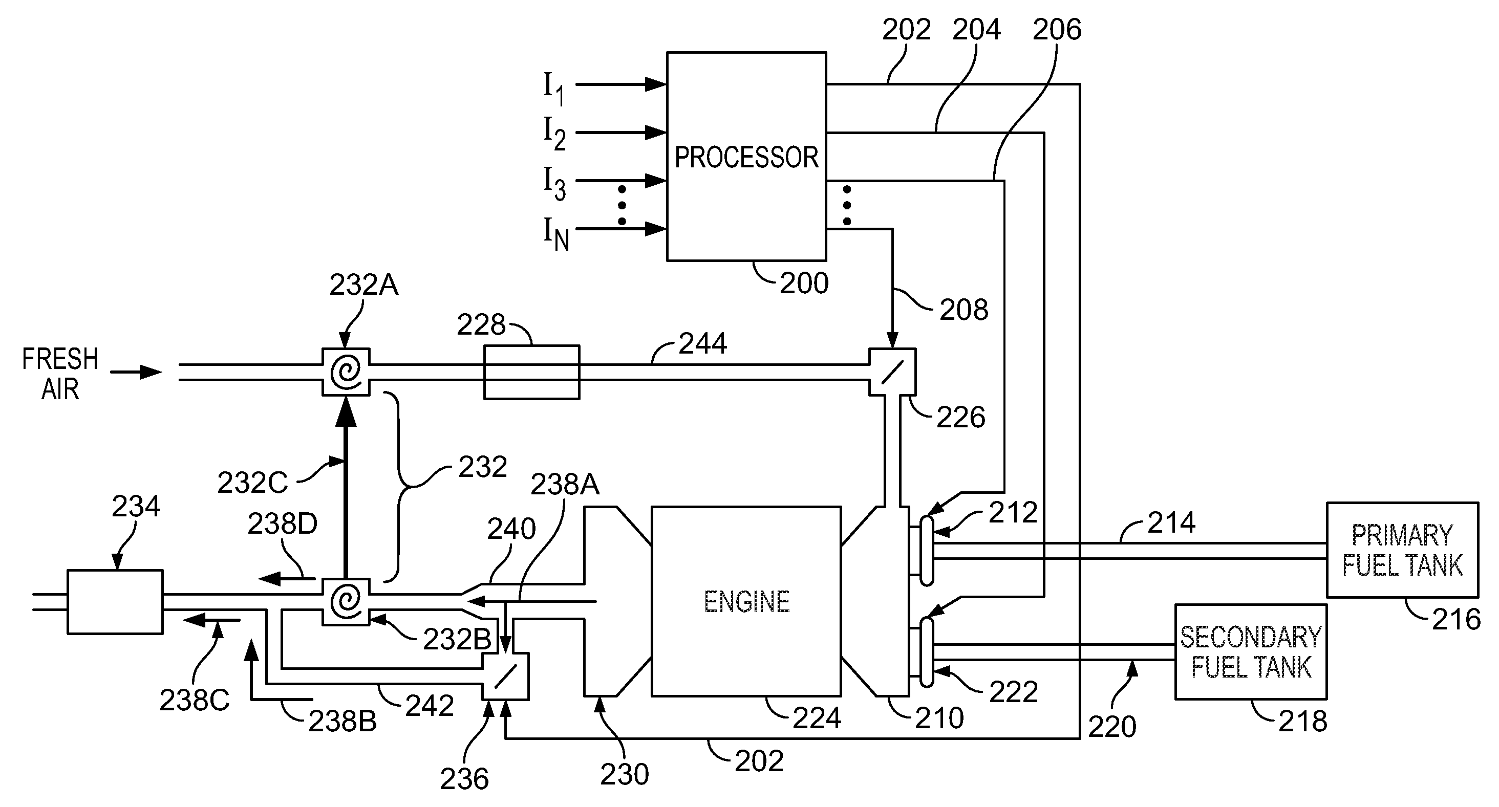
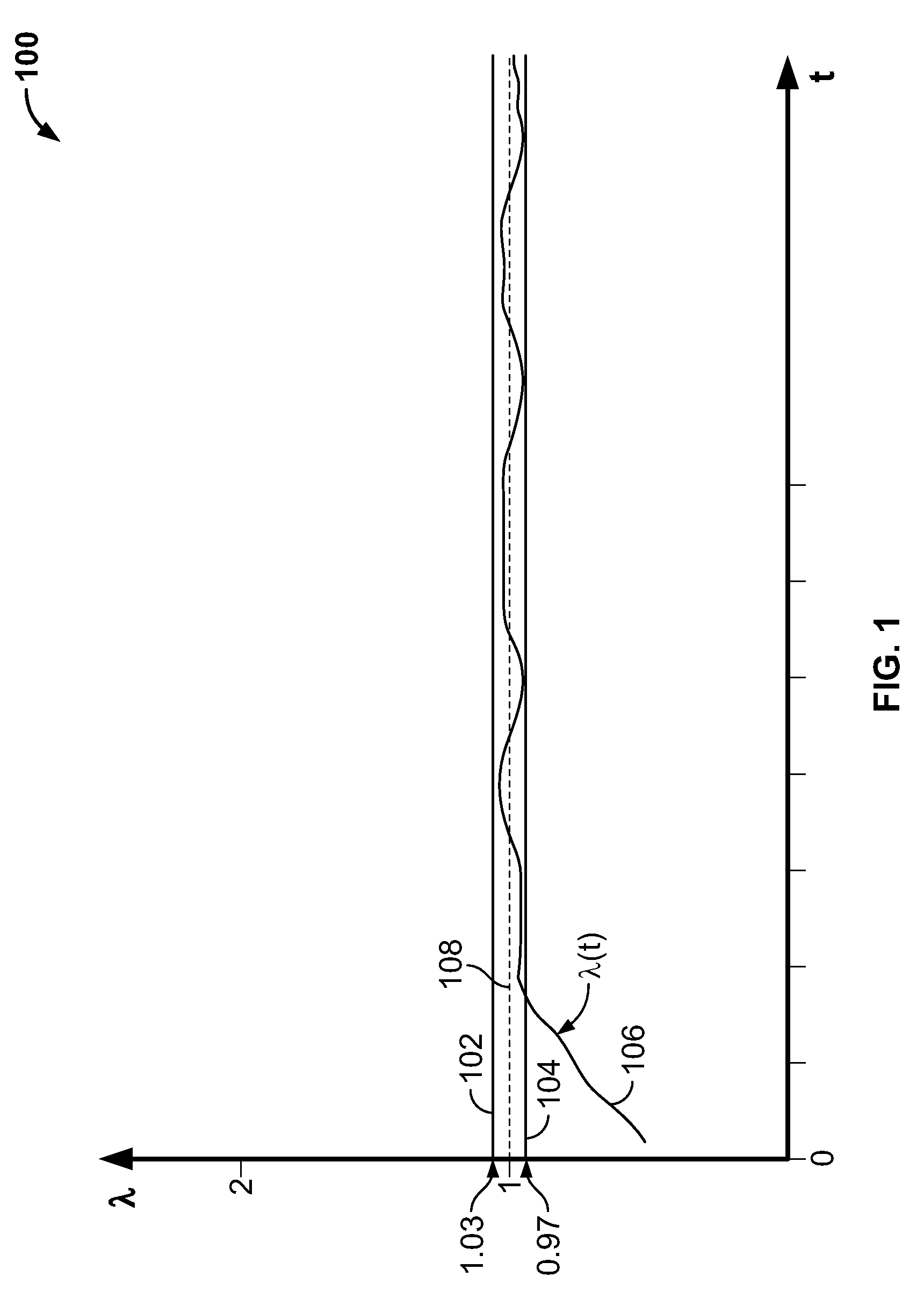
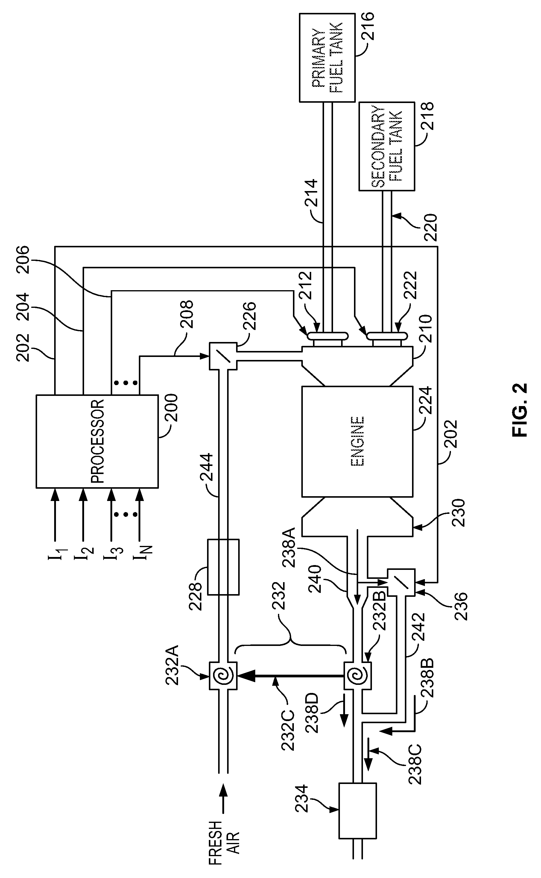
[0029]The present invention provides a device, system and method for controlling a bi-fuel internal combustion engine. The device comprises a processor and an air pump both coupled to the engine and to each other whereby the processor is able to control the air pump and fuel intake of the engine. The air pump, fuel intake of the engine and engine parameters are controlled by the processor to meet power requirements of the engine, achieve acceptable air fuel ratios and avoid forbidden air fuel ratios during operation of the engine. The air fuel ratios are described in terms of λ.

[0030]Acceptable λ values are those values that are desirable based on one or more defined conditions. For example, when the defined condition is the amount of harmful or undesired exhaust gases generated from the combustion of the primary fuel and air or the combustion of a mix of the primary fuel and secondary fuel and air, or the combustion of the secondary fuel and air, acceptable values are those values ...


PUM

PropertyMeasurementUnit
pressureaaaaaaaaaa
operating temperatureaaaaaaaaaa
output poweraaaaaaaaaa

Abstract

A conventional gasoline engine is retrofitted to operate as a bi-fuel engine calibrated to burn Hydrogen gas as a primary fuel and gasoline as a secondary fuel at various acceptable air fuel ratios while avoiding forbidden air fuel ratios. The engine is preferably operated to burn Hydrogen fuel in a charged mode and in a lean mode at certain acceptable air fuel ratios where relatively very little NOx emissions occur. When additional power or acceleration is requested, processor controlled fuel injectors are operated to inject relatively small amounts of gasoline into the engine resulting in a fuel mixture that prevents increases in NOx emissions as the processor controls the engine to operate at a stoichiometric air fuel ratio where a catalytic converter is best able to reduce harmful emissions into the environment. The injection of the secondary liquid gasoline fuel to the gaseous Hydrogen fuel the temperature of the fuels significantly reduces or eliminates backfiring tendency of the engine. The engine has a safety feature in that the Hydrogen fuel is shut off if a leakage of Hydrogen is detected. The engine then operates with gasoline fuel used as a backup fuel.

Description

[0001]This application is being filed on Jun. 7, 2010 concurrently with a commonly owned and related application entitled “Bi-Fuel Engine with Increased Power.”BACKGROUND OF THE INVENTION[0002]1. Field of the Invention[0003]The present invention generally relates to the design and control of internal combustion engines operating on two different fuels and capable of different modes of operations with different air fuel ratios.[0004]2. Description of the Related Art[0005]Internal combustion engines operate on the principle of igniting a mixture of air and gasoline (or other fuel) inside a cylinder to cause combustion within the cylinder where resulting released energy is converted to mechanical energy through the use of a piston inside the cylinder driving a crankshaft. Internal combustion engines are typically naturally aspirated meaning that air is drawn into the engine at atmospheric pressure. As a result of the combustion of the air fuel mixture within a cylinder of the engine, d...

Claims


Application Information

Patent Timeline
Patent Type & Authority Applications(United States)
IPC IPC(8): F02D41/30B23P6/00F02B33/00F02B13/00F02B3/00
CPCF01N3/0814F02D19/066F02D19/081F02D41/0025Y10T29/49233F02M21/0293Y02T10/36Y02T10/32F02D19/0644F02D41/3011Y02T10/30F02D19/06F02D41/30F02D41/00F01N3/08
Inventor GALINDO, JOSE IGNACIOSCHAFFER, KLAUS M.LEITNER, DANIELHEPP, CHRISTOF
Owner H2 IP INVESTMENTS LTD
Why Eureka
Try Eureka