Floating device providing noise reduction properties

a technology of noise reduction and floating devices, which is applied in the direction of sound producing devices, trickle coolers, building components, etc., can solve the problems of high noise reduction costs, severe damage or at least accelerated fatigue of installation, and the worst conditions in cooling towers for any kind of sound dampening installation, etc., to achieve a significant and sustainable level of noise reduction and high mechanical wear resistance

Inactive Publication Date: 2011-12-15
ARMACELL ENTERPRISE GMBH & CO KG
View PDF3 Cites 1 Cited by
  • Summary
  • Abstract
  • Description
  • Claims
  • Application Information

AI Technical Summary

Benefits of technology

[0005]A major object of the present invention thus is to provide a floating noise reduction system or material combination not showing the above mentioned deficiencies but exhibiting a significant and sustainable level of noise reduction over all concerned frequencies and showing an additional drainage effect and high mechanical wear resistance.

Problems solved by technology

Falling or dropping and flowing fluid, especially water, is known to create significant noise that becomes a health and safety concern for work personnel and a nuisance for nearby residents.
A prominent case is in cooling towers of power plants where costly measures have to be taken to reduce the noise.
The conditions in cooling towers are among the worst for any sound dampening installation, as there is a permanent high water impact like from a waterfall moving round in circles.
The resulting force can cause severe damage or at least accelerated fatigue to installations of any kind.
All the a.m. systems are mainly based on metalwork and / or rigid plastics and thus do not possess material immanent dampening properties.
To improve that situation, JP 8200986 claims the use of a combination of water permeable and non-permeable synthetic resin mats, however, also those materials are rather rigid and the drainage properties—despite the claimed drainage ridges—are poor, leading to water agglomeration on top of the mat which will increase the noise level again.
CN 2169107 mentions damping mats and particles; however, the claimed system is not able to provide sufficient structural integrity for the application.
However, those systems are not consequently using the potential of elastic dampening and exhibit deficiencies in floating properties as well as in drainage performance; and some systems again are sensitive to mechanical impact.

Method used


Image

  • Floating device providing noise reduction properties
  • Floating device providing noise reduction properties
  • Floating device providing noise reduction properties

Examples


examples

[0029]Preparation of Test Samples

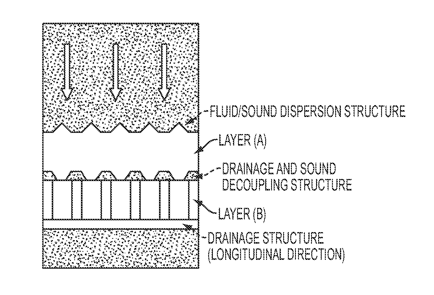
[0030]1. Floating layer (B): an extruded, expanded and cut PET board of 25 mm thickness and 1000×1000 mm width (ArmaStruct®, Armacell, Münster, Germany) was coated with a silicone adhesive layer (ELASTOSIL® R plus 4700, Wacker Chemie, München, Germany) to give the floating part of the system. A sinus shape ridge structure (distance peak to peak of 35 mm) was applied to one surface by thermoforming embossing and pin holes of 20 mm diameter were drilled into the board in a distance of 80 mm.

[0031]2. Sponge like open cell absorbing layer (A): A rubber compound (Armaprene® N H, Armacell, Münster, Germany) was extruded, expanded and cut to an open cell foam mat of 25 mm thickness and 1000×1000 mm width and then laminated onto the plain surface of (B) as single or double layer by heating the composite up to 120° C. in a hot air oven, using the a.m. adhesive.

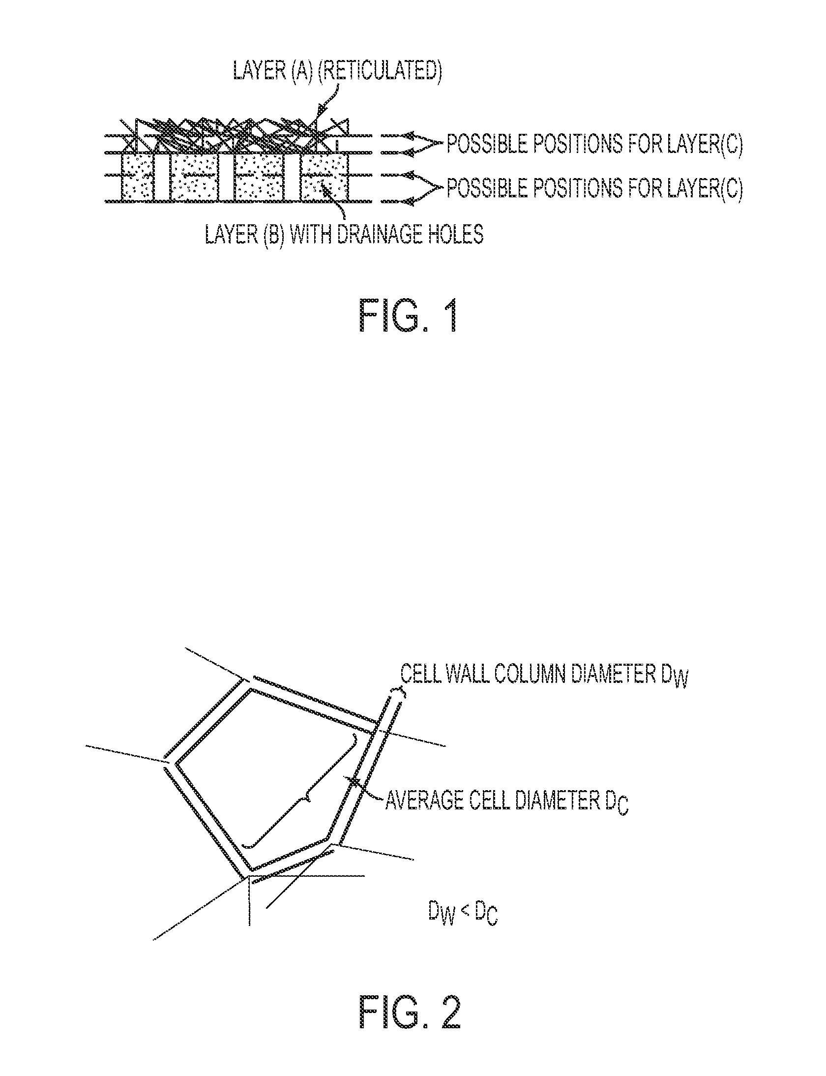
[0032]3. Skeleton structure open cell absorbing layer (A): A reticulated polyurethane foam mat of th...


PUM


Abstract

The present invention relates to a floating noise reduction system for moving and/or falling fluids, the process for manufacturing of such system and the use of such system.

Description

CROSS REFERENCE TO RELATED APPLICATIONS[0001]This application claims priority from European patent application No. 10 163 520.9-2213 filed on May 21, 2010, all of which is incorporated herein by reference in its entirety for all purposes.FIELD OF THE INVENTION[0002]The present invention relates to a floating noise reduction system for moving and / or falling fluids, the process for manufacturing of such system and the use of such system.BACKGROUND OF THE INVENTION[0003]Falling or dropping and flowing fluid, especially water, is known to create significant noise that becomes a health and safety concern for work personnel and a nuisance for nearby residents. A prominent case is in cooling towers of power plants where costly measures have to be taken to reduce the noise. The conditions in cooling towers are among the worst for any sound dampening installation, as there is a permanent high water impact like from a waterfall moving round in circles. The resulting force can cause severe dam...

Claims


Application Information

Patent Timeline
Patent Type & Authority Applications(United States)
IPC IPC(8): E04B1/84
CPCG10K11/162F28C1/10Y02B30/70
Inventor QUANTE, HERIBERTSWIFT, MARKWEIDINGER, JURGEN
Owner ARMACELL ENTERPRISE GMBH & CO KG
Why Eureka
Try Eureka