Non-contact power feeding device

Inactive Publication Date: 2011-12-15
SHOWA AIRCRAFT INDUSTRY
View PDF5 Cites 24 Cited by
  • Summary
  • Abstract
  • Description
  • Claims
  • Application Information

AI Technical Summary

Benefits of technology

[0056]Third, these can be readily realized with a simple structure and economic advantage.
[0057]In the non-contact power feeding device of the present invention, the above-described first and second effects can be readily realized with a simple structure whereby the resonant coil is wound in parallel on the same plane as the power transmission coil and/or the power receiving coil.
[0058]In other words, in the non-contact power feeding device of the present invention, the resonant coil and the power transmission coil and/or the resonant coil and the power receiving coil are united (integrated) without being overlapped as a separate body in the magnetic path. Thus, as compared to the above-described non-contact power feeding device of prior application, the non-contact power feeding device of the present invention is excellent in cost in vi

Problems solved by technology

However, even in such a flat structure, it has been pointed out that there is a problem that the power transmission coil 3 and the resonant coil 16, and the power receiving coil 8 and the resonant coil 16 are disposed to overlap each other in the magnetic path and as a result, the coil is

Method used


Image

  • Non-contact power feeding device
  • Non-contact power feeding device
  • Non-contact power feeding device

Examples


embodiment

Preferred Embodiment

[0124]A preferred embodiment of the present invention will now be described.

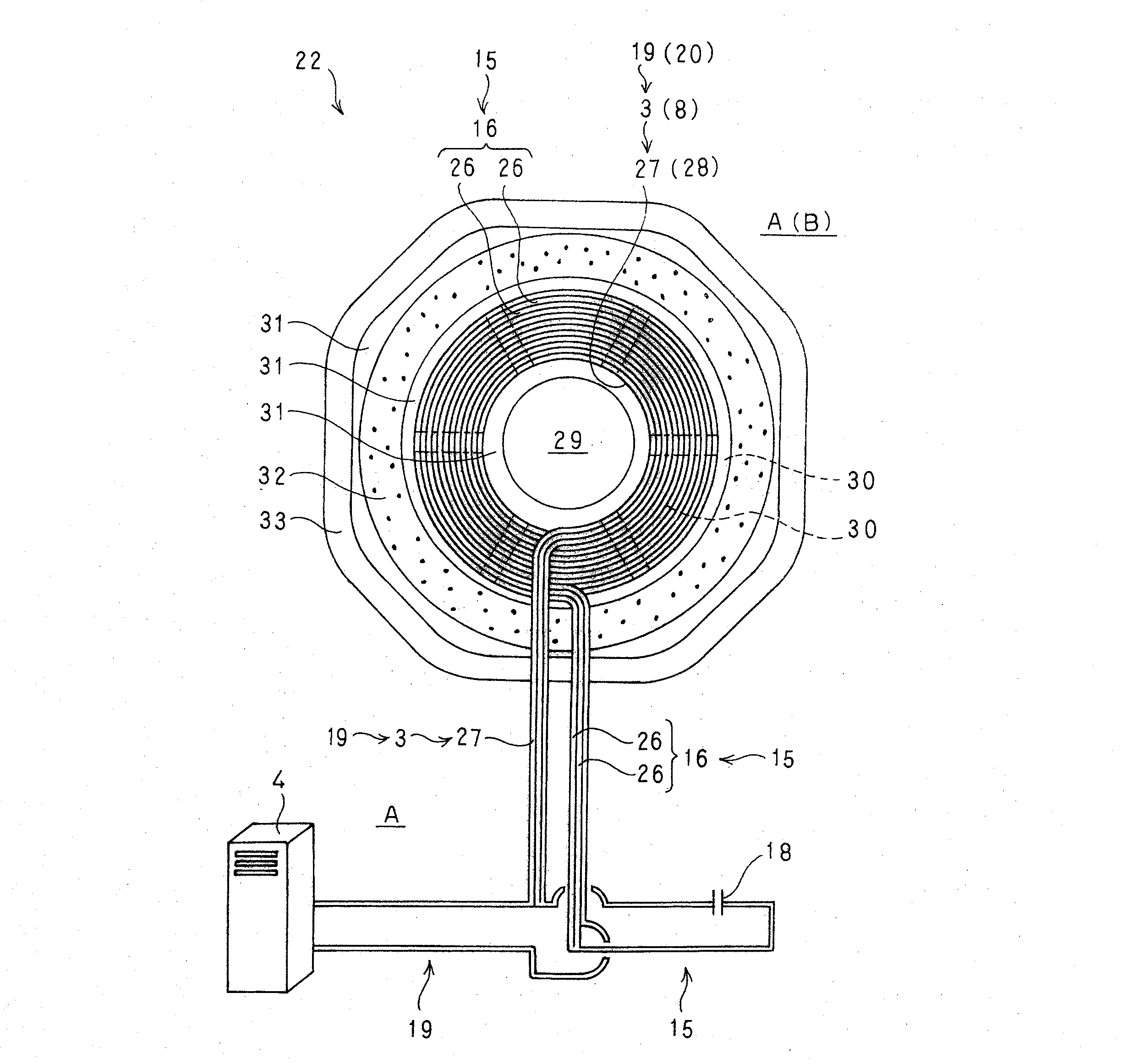
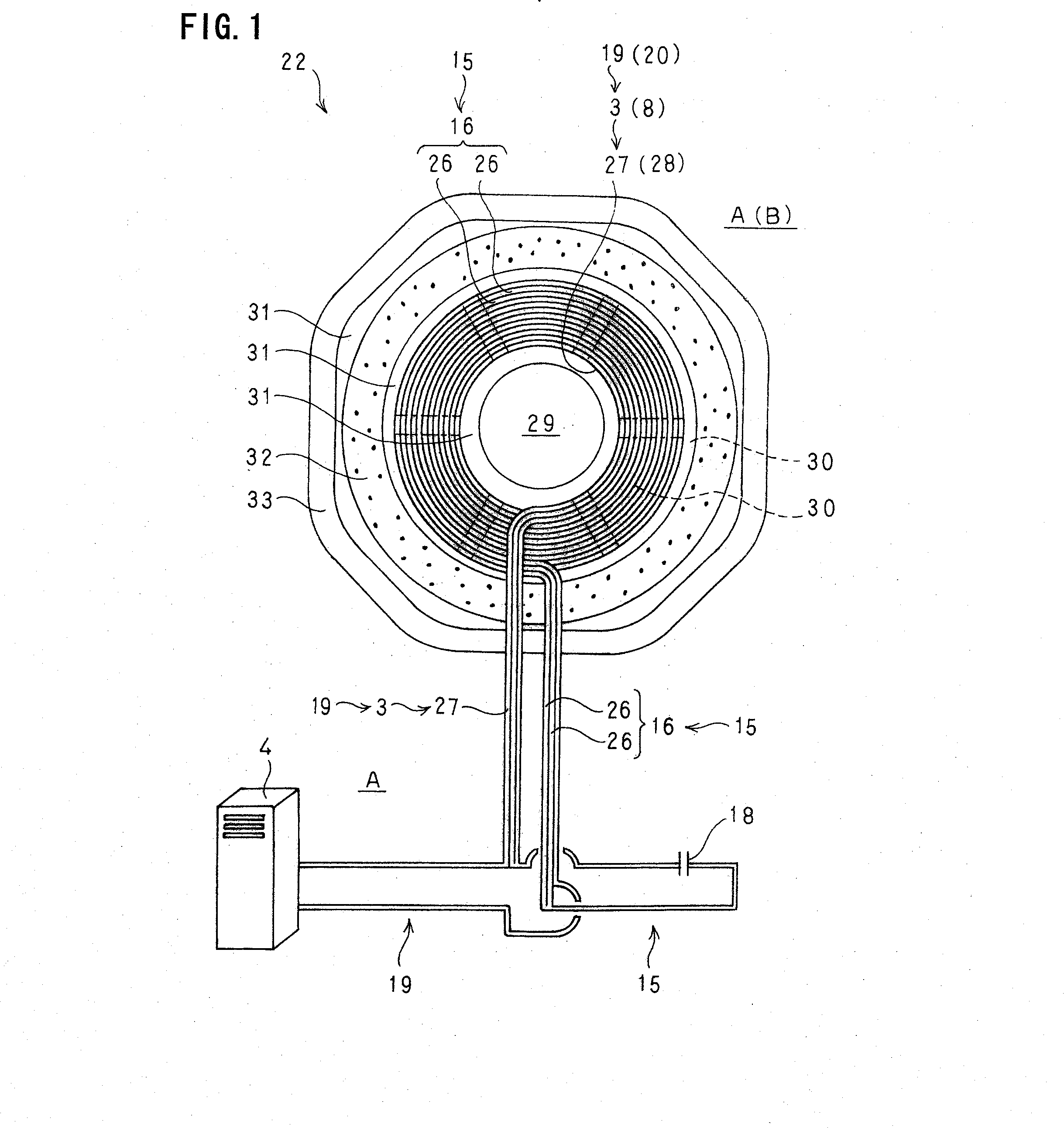
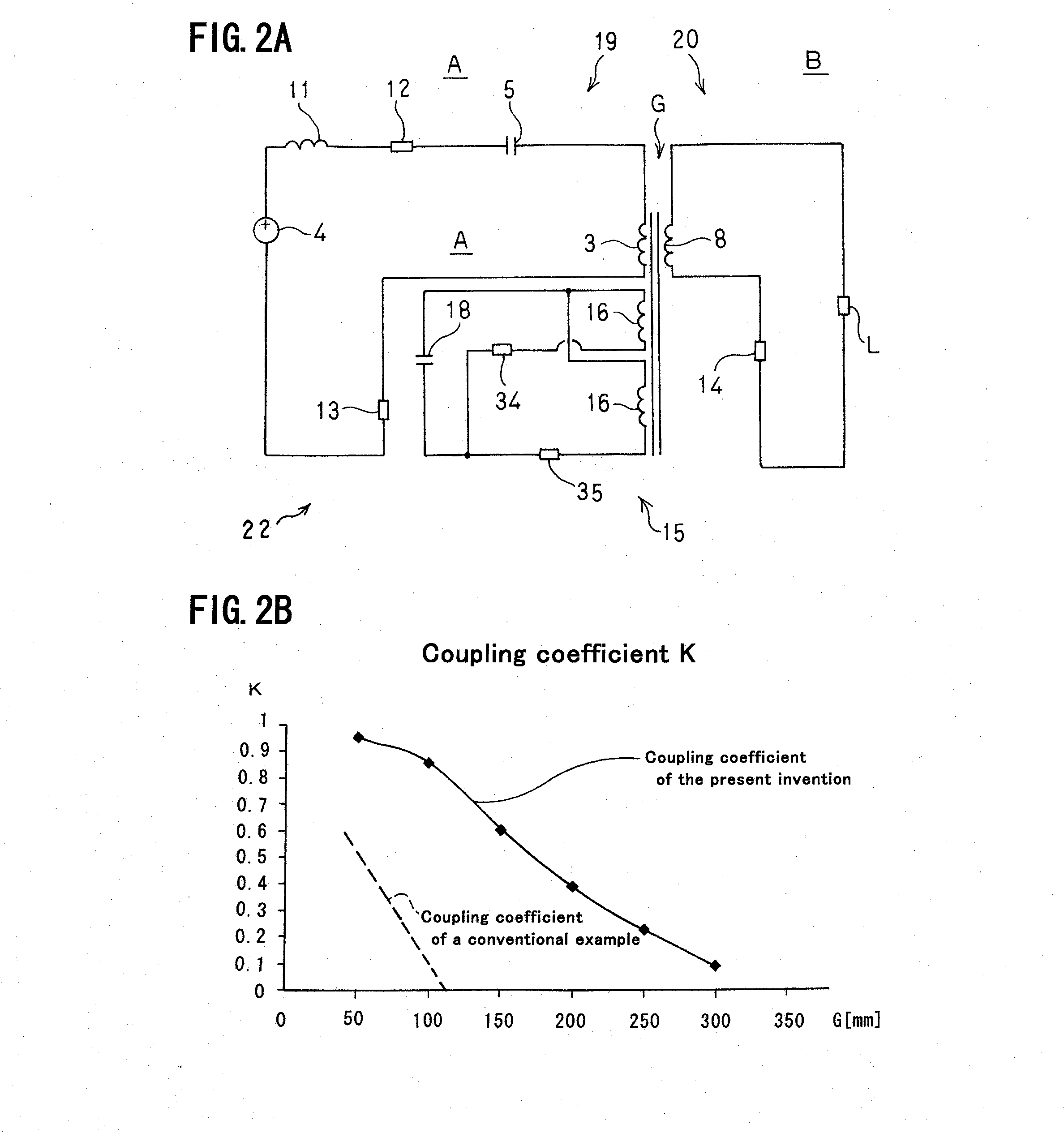
[0125]FIG. 2B is a graph showing the data of each coupling coefficient of an embodiment of the non-contact power feeding device 22 of the present invention as shown in FIG. 2A and the conventional non-contact power feeding device 1 as shown in FIGS. 4A and 4B.

[0126]Even the comparison of the experimental data by the graph supports that the non-contact power feeding device 22 is better than the conventional non-contact power feeding device 1 in the coupling coefficient which shows the degree of electromagnetic coupling between the magnetic circuit coils.

[0127]This experimental data was obtained by computing the coupling coefficient K for each spacing size based on the actual measurement value while changing the spacing size of the air gaps G of the non-contact power feeding device 22 and the non-contact power feeding device 1.

[0128]According to the experimental data obtained, in the conven...


PUM


Abstract

In a non-contact power feeding device of the present invention, power is fed through an air gap with no contact from a power transmission coil of a power feeding side circuit to a power receiving coil of a power receiving side circuit, which are located to face each other, based on a mutual induction effect of electromagnetic induction. In such a non-contact power feeding device, a resonant coil of a repeating circuit is disposed on the power transmission coil side and/or the power receiving coil side. The resonant coil is wound in parallel on the same plane as the power transmission coil and/or the power receiving coil. The resonant coil the power transmission coil and the power receiving coil are respectively composed of a single insulated conducting wire or a number of insulated conducting wires.

Description

BACKGROUND OF THE INVENTION[0001]The present invention relates to a non-contact power feeding device, and more particularly to a non-contact power feeding device adapted to feed power, with no contact, to a power receiving side which is mounted on a vehicle and the like from a power feeding side which is fixedly disposed on the ground side.[0002]A non-contact power feeding device adapted to feed power from outside to, for example, a battery of an electric vehicle without any mechanical contact such as a cable has been developed based on the demand and this device is in practical use.[0003]In such a non-contact power feeding device, power is fed through an air gap of about tens of millimeters to hundreds of millimeters to a power receiving coil mounted on an electric vehicle or other vehicle from a power transmission coil which is fixedly disposed on the ground side, based on a mutual induction effect of electromagnetic induction (refer to FIG. 5 described below).[0004]FIG. 4 shows a...

Claims


Application Information

Patent Timeline
IPC IPC(8): H01F38/14B60L5/00
CPCB60L11/182Y02T10/7005B60L2200/26Y02T90/14Y02T90/122B60L53/12B60L53/122Y02T10/70Y02T10/7072H01F38/14H02J50/12Y02T90/12
Inventor YAMAMOTO, KITAOSATO, TAKESHIABE, KEISUKEMOCHIZUKI, MASASHIOKIYONEDA, YASUYUKI
Owner SHOWA AIRCRAFT INDUSTRY
Why Eureka
Try Eureka