Isolated switching power supply apparatus

a technology of switching power supply and isolated circuit, which is applied in the direction of electric variable regulation, process and machine control, instruments, etc., can solve the problems of difficult to flexibly authorize the primary-side control circuit or the secondary-side control circuit, complicated circuit configuration, etc., and achieve the effect of reducing the footprint and the cost of the isolated switching power supply apparatus

Active Publication Date: 2011-12-15
MURATA MFG CO LTD
View PDF6 Cites 91 Cited by
  • Summary
  • Abstract
  • Description
  • Claims
  • Application Information

AI Technical Summary

Benefits of technology

[0021]According to various preferred embodiments of the present invention, the following advantages and effects are obtained. An auxiliary power supply for a secondary-side control circuit is not needed. Since both a primary side and a secondary side can take the lead in p

Problems solved by technology

Therefore, a circuit configuration becomes complicated.
However, it is difficult to flexibly authorize the primary-side contr

Method used


Image

  • Isolated switching power supply apparatus
  • Isolated switching power supply apparatus
  • Isolated switching power supply apparatus

Examples


first preferred embodiment

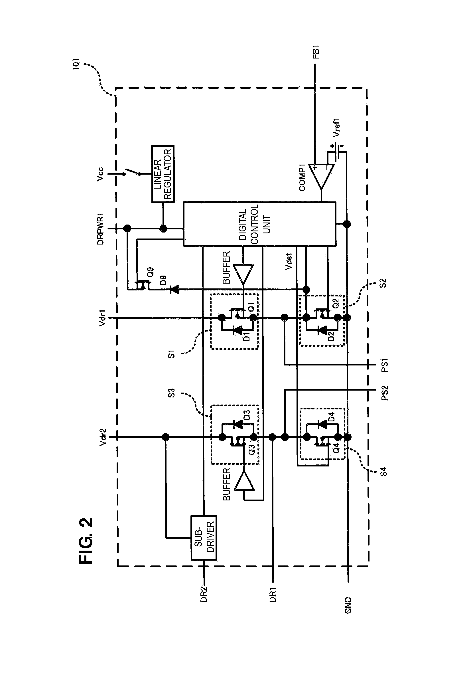
[0043]FIG. 2 is an internal block diagram of a control IC 101 included in an isolated switching power supply apparatus according to the first preferred embodiment of the present invention. The control IC 101 preferably includes series circuits and a digital control unit. One of the series circuits includes a first switching circuit S1 and a second switching circuit S2. The other one of the series circuits includes a third switching circuit S3 and a fourth switching circuit S4. The first switching circuit S1 includes a first switching element Q1 and a first diode D1 that are connected in parallel. The second switching circuit S2 includes a second switching element Q2 and a second diode D2 that are connected in parallel. The third switching circuit S3 includes a third switching element Q3 and a third diode D3 that are connected in parallel. The fourth switching circuit S4 includes a fourth switching element Q4 and a fourth diode D4 that are connected in parallel. The digital control u...

second preferred embodiment

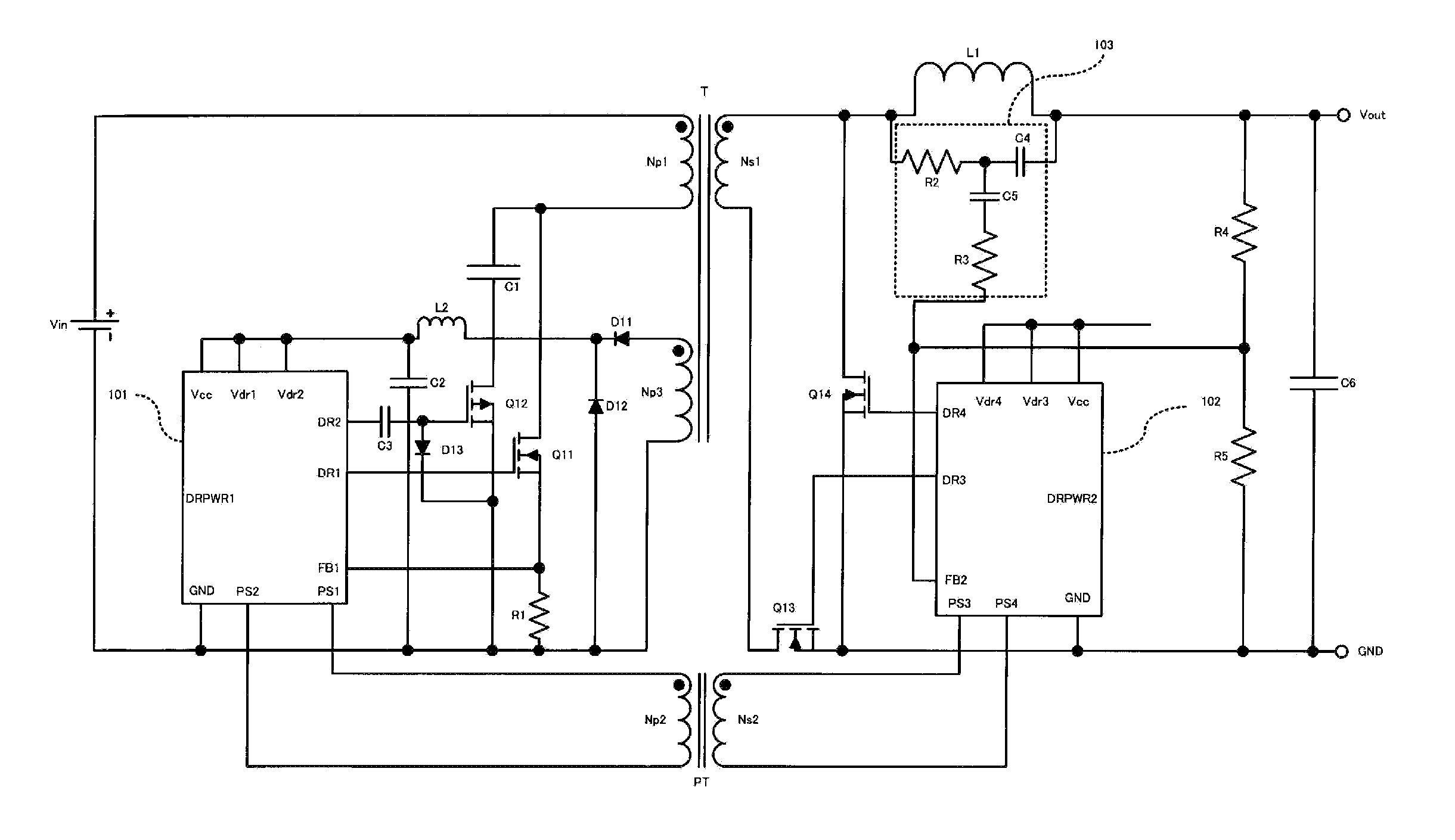
[0095]FIG. 20 is a circuit diagram of an isolated DC-DC converter according to the second preferred embodiment of the present invention preferably including the control IC illustrated in FIG. 2.

[0096]The difference between an isolated DC-DC converter according to the second preferred embodiment illustrated in FIG. 20 and an isolated DC-DC converter according to the first preferred embodiment illustrated in FIG. 3 is that a seventh capacitor C7 and an eighth capacitor C8 are preferably provided instead of the pulse transformer PT. In the first preferred embodiment, a pulse signal including a fundamental wave component of a frequency higher than a switching frequency is preferably transmitted as a timing signal between the primary side and the secondary side via the pulse transformer PT having a relatively small excitation inductance. On the other hand, in the second preferred embodiment, a pulse signal is preferably transmitted between the primary side and the secondary side using ca...


PUM


Abstract

A control IC including a full-bridge circuit is disposed on a primary side and a secondary side. Bidirectional communication is performed between the primary side and the secondary side in a state in which they are isolated. A control signal output from the primary side or the secondary side earlier is preferentially processed. As a result, the authority to control a switching element can be freely given to a primary-side control IC or a secondary-side control IC, and any control processing can be performed with software.

Description

BACKGROUND OF THE INVENTION[0001]1. Field of the Invention[0002]The present invention relates to an isolated switching power supply apparatus arranged to perform control processing in a plurality of modes including a soft start mode, a sleep mode, a hiccup mode, and a latch mode.[0003]2. Description of the Related Art[0004]In isolated switching power supply apparatuses, in order to use different ground potentials in a primary circuit and a secondary circuit and to satisfy a safety standard, a primary side and a secondary side are isolated using a transformer. In order to control an output voltage and an output current of the secondary side, the output voltage and the output current of the secondary side are detected and are then fed back to the primary side and a switching circuit on the primary side is controlled based on the detected output voltage and the detected output current. At that time, a feedback circuit also needs to achieve the isolation between the primary side and the...

Claims


Application Information

Patent Timeline
IPC IPC(8): H02M3/24
CPCY02B70/1475H02M3/33592Y02B70/10H02M1/08
Inventor MATSUMOTO, TADAHIKO
Owner MURATA MFG CO LTD
Why Eureka
Try Eureka