
Electrical Heating Catalyzer Having Honeycomb Structure

a technology of electric heating and catalyzer, which is applied in the direction of process control, separation process, instruments, etc., can solve the problems of damage to the honeycomb body, non-uniform temperature of the base material, and problems that are considered especially noticeable, so as to achieve uniform heating of the overall base material

Active Publication Date: 2011-12-15
DENSO CORP
View PDF4 Cites 18 Cited by
  • Summary
  • Abstract
  • Description
  • Claims
  • Application Information

AI Technical Summary

Benefits of technology

[0009]An embodiment provides an electrical heating catalyzer capable of uniformly heating a base material while achieving rapid temperature rise.
[0011]Regarding this point, as a first aspect of the embodiment, a path-specific current that flows through the base material when a predetermined voltage is applied or an inter-electrode resistance in the base material is detected for each current path. Then, the path-specific current or the inter-electrode resistance of each current path is compared, and an energization timing for each current path is individually controlled based on comparison results. In this instance, as a result of comparison of the path-specific current or the inter-electrode resistance of each current path, variation in internal resistance of the base material among the current paths can be found, and the energization timing of each current path can be individually controlled taking into consideration the variation among current paths. Therefore, even when a difference in inter-electrode resistance of each current path occurs as a result of placement aspects of the electrodes, individual differences and aging of the base material, and the like before heating of the base material is started, heating can be performed to resolve the difference after heating is started, and temperature distribution in the base material can be made uniform. As a result, localized concentration of thermal stress in the base material can be suppressed. At this time, even when high power is introduced to the base material to achieve early activation, damage to the base material and the like can be suppressed. As a result, the base material can be uniformly heated while achieving rapid temperature rise.
[0013]In the base material having NTC characteristics, internal resistance gradually decreases (energization current increases) when temperature increases with the start of energization. When the size of inter-electrode resistance differs among the current paths, the current in a current path having the smaller inter-electrode resistance becomes larger than those of other current paths, and heat is concentrated in the region having the smaller inter-electrode resistance. Regarding this point, according to the above-described configuration, when the size of inter-electrode resistance differs among the current paths before heating of the base material is started, resistance value decreases in the current path having the larger inter-electrode resistance while resistance value is maintained in the current path having the smaller inter-electrode resistance, immediately after heating is started. Therefore, the difference in inter-electrode resistance can be resolved after heating of the base material is started, and temperature distribution in the base material can be made uniform.
[0016]According to the above-described embodiment, the path-specific currents and the inter-electrode resistances can be matched by a simple method between the current path of which energization is started first and the current path of which energization is started later. For example, a relationship between the difference in path-specific current or inter-electrode resistance among the current paths and the energization delay time can be set in advance, and the energization delay time can be decided based on the relationship.
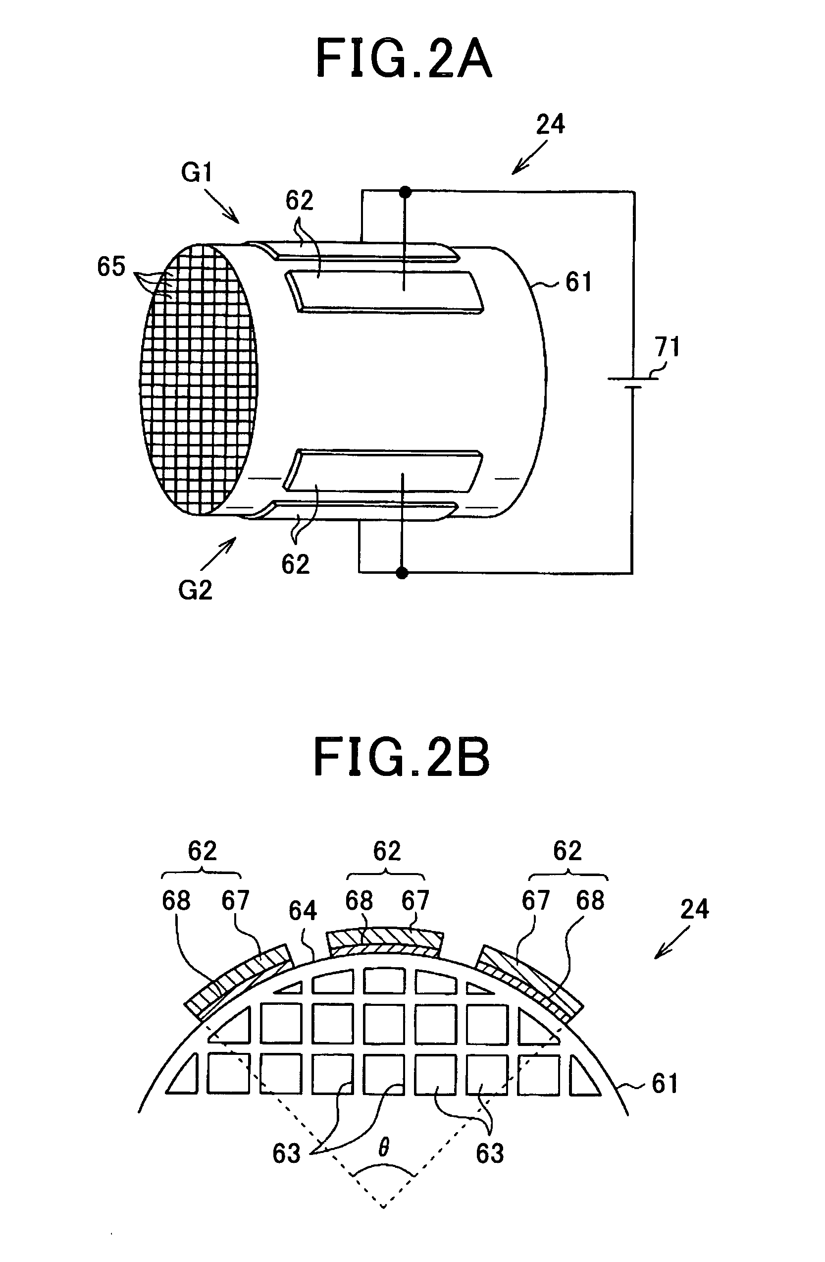
[0025]In other words, when energization of the base material is performed over a plurality of current paths, depending on the placement of electrodes, the number and positions of the current paths, and the like, uneven heating occurs in the base material, resulting in non-uniform temperatures. Regarding this point, according to the above-described configuration, because the current path to be energized can be switched each time among the plurality of current paths extending in mutually intersecting directions, uneven heating of the base material can be suppressed. In other words, when a plurality of current paths are provided such as to extend in the same direction, portions through which current does not easily flow (in other words, portions that are not easily heated) are formed, such as between the current paths. As a result of switching being performed accordingly among the mutually intersecting current paths as described above, portions through which current does not easily flow (in other words, portions that are not easily heated) are no longer easily formed. As a result, the base material can be uniformly heated.
[0027]According to the above-described configuration, portions through which current does not easily flow (in other words, portions that are not easily heated) are eliminated in the base material having a circular columnar shape, and uniform heating of the overall base material can be achieved.

Problems solved by technology

In this instance, because the honeycomb body is not uniformly heated, thermal stress is concentrated locally, thus possibly leading to problems such as damage to the honeycomb body.
Such problems are considered especially noticeable when the introduced energy is increased to achieve early activation (early temperature rise) of the catalyzer, as described above.
In this instance, when an inter-electrode resistance of each current path differs, a difference in path-specific current when voltage is applied occurs, causing non-uniform temperatures in the base material.
When the path-specific current of each current path is detected, because energization is not subsequently immediately started for all current paths, temperature rise in the base material caused by temporary energization during detection of the path-specific current is not desirable.
In other words, when energization of the base material is performed over a plurality of current paths, depending on the placement of electrodes, the number and positions of the current paths, and the like, uneven heating occurs in the base material, resulting in non-uniform temperatures.
As a result of switching being performed accordingly among the mutually intersecting current paths as described above, portions through which current does not easily flow (in other words, portions that are not easily heated) are no longer easily formed.

Method used


Image

  • Electrical Heating Catalyzer Having Honeycomb Structure
  • Electrical Heating Catalyzer Having Honeycomb Structure
  • Electrical Heating Catalyzer Having Honeycomb Structure

Examples


Embodiment Construction

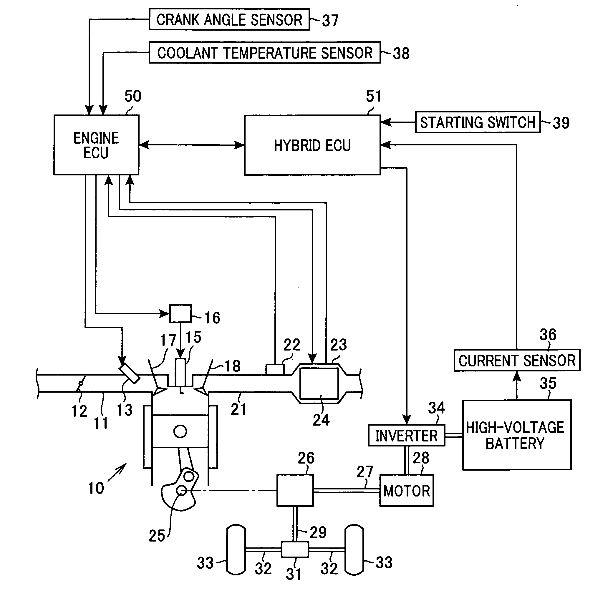
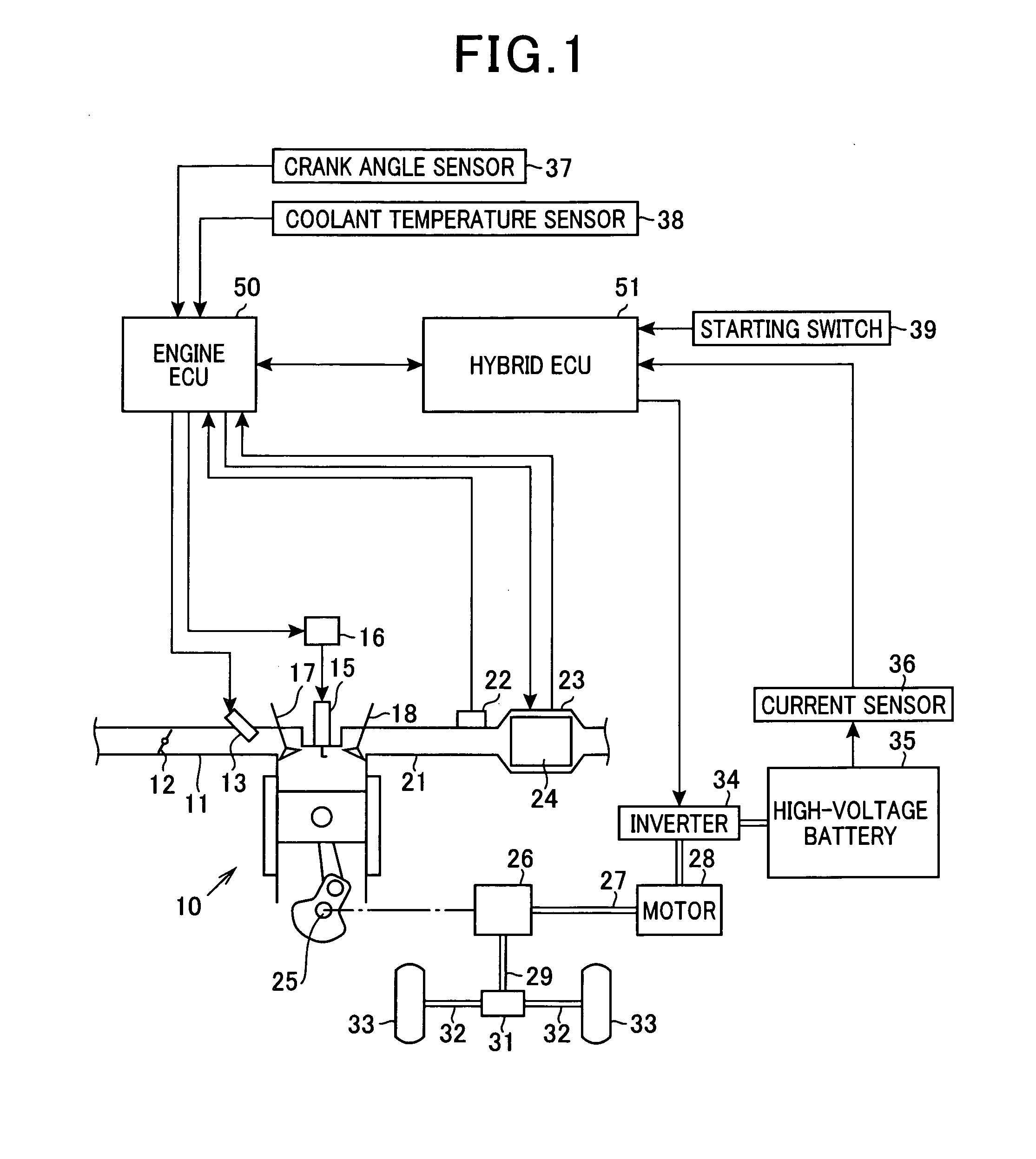
[0040]An embodiment will hereinafter be described with reference to the drawings. According to the present embodiment, a control device in a vehicle control system of a hybrid car that uses an engine and a motor as power sources is specified. In the vehicle control system, an engine electronic control unit (engine ECU) and a hybrid electronic control unit (hybrid ECU) are provided. With the engine ECU serving as the core, fuel injection amount control, ignition timing control, and the like are performed in the engine. With the hybrid ECU serving as the core, motor control and overall system control including motor control are performed. FIG. 1 is a configuration diagram of an overview of the overall vehicle control system.

[0041]In FIG. 1, an engine 10 is a spark-ignition-type multi-cylinder gasoline engine. An electrically driven throttle valve 12 is provided in an intake pipe 11, and an injector 13 serving as a fuel injection means is provided in an engine intake port connected to ...


PUM

PropertyMeasurementUnit
Temperatureaaaaaaaaaa
Electrical resistanceaaaaaaaaaa

Abstract

A honeycomb body of a honeycomb structure is made of ceramic, and a plurality of electrodes are provided apart from one another on a surface of the honeycomb body. In the honeycomb body, energization is performed for each of a plurality of current paths Xa to Xc formed by the plurality of electrodes, thereby heating the honeycomb body. A controlling device detects heater current Ia, Ib, and IC that flow when a predetermined voltage is applied for each of the plurality of current paths Xa, Xb, and Xc, and controls an energization timing of each current path Xa to Xc based on the detection results.

Description

CROSS REFERENCE TO RELATED APPLICATION[0001]This application is based on and claims the benefit of priority from earlier Japanese Patent Application No 2010-133551 filed on Jun. 11, 2010 the description of which is incorporated herein by reference.TECHNICAL BACKGROUND[0002]1. Field of the Invention[0003]The present invention relates to an electrical heating catalyzer, in particular, to an electrical heating catalyzer capable of uniformly heating base material thereof.[0004]2. Description of the Related Art[0005]Conventionally, a catalyzer is used as an exhaust emission control device for purifying exhaust from an engine. The catalyzer is configured by a catalyst, such as Pt, Pd, or Rh, being supported by a ceramic honeycomb body (base material), and is capable of achieving desired exhaust emission control performance by being held at a predetermined activation temperature (such as about 400° C.).[0006]For example, as a catalyzer disclosed in JP-A-H3-295184, an electrical heating cat...

Claims


Application Information

Patent Timeline
IPC IPC(8): B01D53/94
CPCB01D53/9454B01D2255/1021B01D2255/1023Y02T10/22B01D2255/92F01N3/2026Y02T10/26B01D2255/1025Y02T10/12Y02A50/20
Inventor KAWASE, TOMOOSUGIURA, KOJI
Owner DENSO CORP
Learn More