Specimen freezing rate regulator device

a regulator device and freezing rate technology, applied in the field of specimen freezing rate regulator devices, can solve the problems of reducing the survival of cells upon thawing, affecting the efficiency of cell survival,

Inactive Publication Date: 2011-12-22
COOL LAB LLC
View PDF14 Cites 38 Cited by
  • Summary
  • Abstract
  • Description
  • Claims
  • Application Information

AI Technical Summary

Benefits of technology

[0008]In some embodiments, the base contains a central cavity that may contain air space. In other embodiments, the container central cavity may contain a material that will provide a quantity of thermal energy that will influence the rate of thermal energy reduction of the specimen vial contents during the temperature reduction process.

Problems solved by technology

If the freezing of the intracellular solution is coincident with the appropriate level of water content, the size of the crystals resulting from the crystallization of the remaining intracellular water will not be sufficient to cause damage to the cell.
If, however, the degree of water removal from the cell is excessive, or if the exposure of the cells to concentrated extracellular solutes is too long in duration, damage to cellular structures will incur, resulting in reduced cell survival upon thawing.
Although the regulated freezing chambers are effective in reproducing the desired temperature reduction rate, the cost of the units can be prohibitive.
In addition, the requirement for freezing device availability is not uniform in typical laboratory environments, resulting in freezing backlogs until the chambers become available.
This method, however, provides inconsistent and sometimes inferior survival rates and most importantly post-thaw cell function or such methods can result in an unintentional and undesirable selection of sub-populations of cells.
The method, however, introduces various burdensome problems.
The alcohol change requirement adds a reoccurring cost to the product in the form of the requirement for a supply of fresh alcohol and the cost of proper toxic waste disposal of the expired alcohol.
The requirement for alcohol imposes a potential fire hazard during the alcohol exchange phase or in the event of spillage or breakage of the device.
The relatively large thermal mass of the assembly also places a burden on the mechanical freezer causing a transient rise in the interior temperature of the freezer.
If archival samples are present in the vicinity of the freezing unit, the samples may experience a thermal cycling that can contribute to premature degradation of the samples.

Method used


Image

  • Specimen freezing rate regulator device
  • Specimen freezing rate regulator device
  • Specimen freezing rate regulator device

Examples


experiment 1

y of Specimen Freezing Cycle

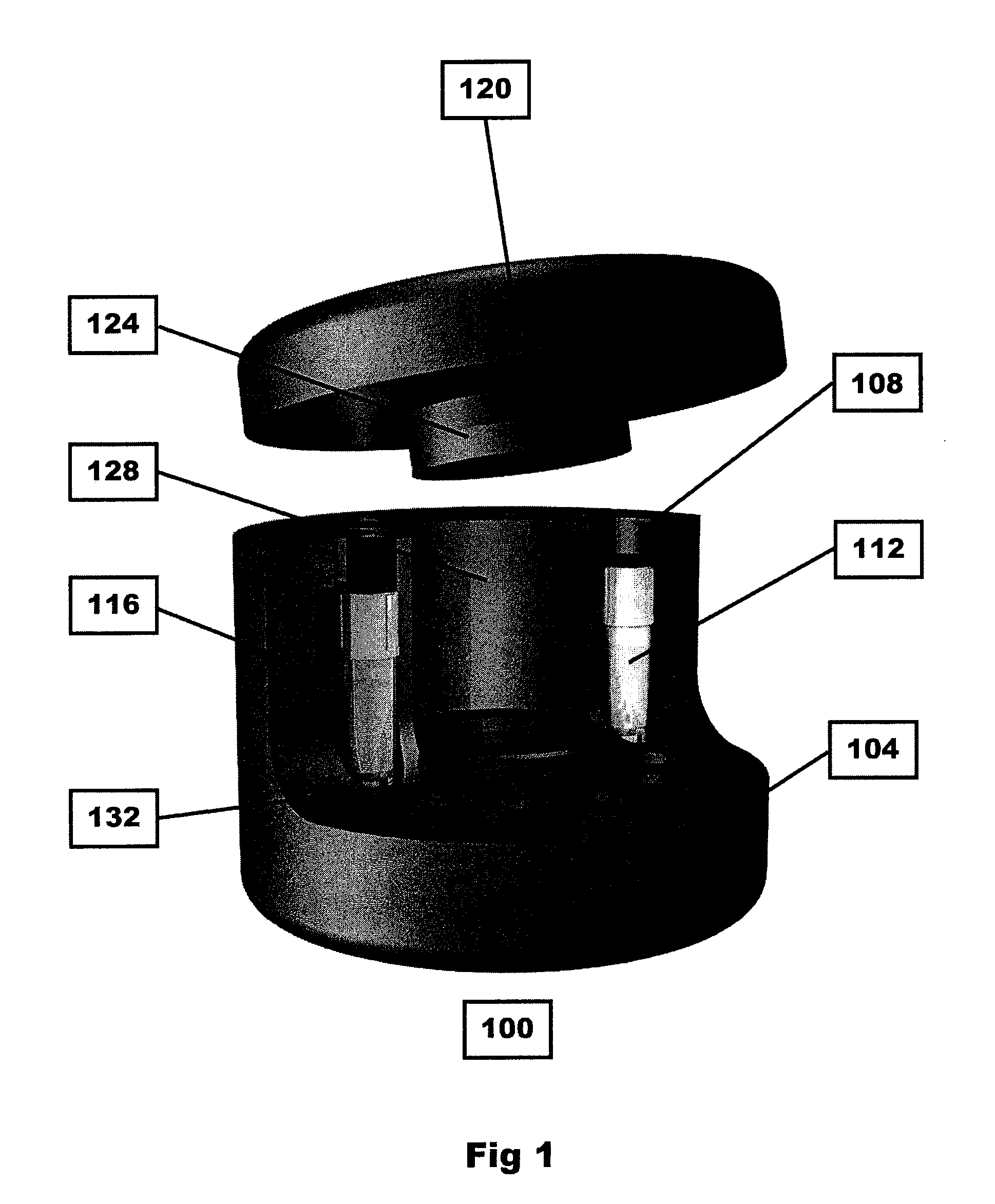
[0030]With reference to FIG. 3, the results from an experiment are shown. This experiment was conducted using a prototype device 100 as shown in FIG. 1. The device 100 was loaded with 12 specimen vials containing 1 ml of cryoprotectant solution each. The device 100 was then closed by replacing the cover, and the device and cover were placed in a −80° C. freezer compartment. The cryoprotectant load of one vial was monitored using a thermocouple probe introduced through the cover of the device and through the screw-cap lid of the specimen vial. The temperature of the cryoprotectant solution was recorded using an electronic data recorder that collected sample data at 10 second intervals. Following a four hour interval, the assembly was removed from the freezer disassembled and the device and sample vials re-equilibrated to 20° C. The sample vials were re-loaded and the freezing cycle described was repeated a total of 5 times. The combined graphic plots of th...

experiment 2

ezing Rate Regulator with Central Ballast Mass

[0031]With reference to FIG. 4, the results from an experiment are shown. This experiment was conducted using a prototype device 100 with and without a ballast 132, as shown in FIG. 1. The device 100 was loaded with 12 specimen vials containing 1 ml of cryoprotectant solution each, then closed by replacing the cover after which the assembly was placed in a −80° C. freezer compartment. The cryoprotectant load of one vial was monitored using a thermocouple probe introduced through the cover of the device and through the screw-cap lid of the specimen vial. The temperature of the cryoprotect solution was recorded using an electronic data recorder that collected sample data at 10 second intervals. Following a four hour interval, the assembly was removed from the freezer disassembled and the device and sample vials re-equilbrated to 20° C.

[0032]Four separate freezing cycles are shown in which the central cavity of the device contained no addit...


PUM

PropertyMeasurementUnit
volumesaaaaaaaaaa
temperatureaaaaaaaaaa
thermalaaaaaaaaaa

Abstract

A system and method for concurrently and uniformly removing thermal energy from a specimen sample. A thermal insulating device is provided comprising an insulating material, the device having a plurality of chambers for receiving specimen samples, the device further includes a thermal ballast whereby the rate of thermal energy removal is controlled and influenced by the thermal ballast.

Description

FIELD OF THE INVENTION[0001]This invention relates to devices that will regulate the rate of heat loss from sample or specimen vials contained within, following placement of the assembly into a lower temperature environment, thereby producing the desired temperature reduction profile. In particular, the device is intended to be used with live cell suspensions to provide the appropriate freezing rate for enhanced cell survival following cryogenic storage.BACKGROUND OF THE INVENTION[0002]Common and accepted methods for long-term storage of tissues and live cells typically involve long-term storage of the sample at a temperature at which molecular activity is significantly reduced. At sufficiently reduced temperatures, the specimens can be stored most likely indefinitely without degradation. The recovery of live cells preserved by this method is dependent upon minimizing injurious ice crystal growth in the intracellular region both during the freezing process and the thawing process. A...

Claims


Application Information

Patent Timeline
Patent Type & Authority Applications(United States)
IPC IPC(8): F25D25/00B23P17/04
CPCA01N1/0263A61B10/0096Y10T29/49826B01L7/50B01L3/5082
Inventor SCHRYVER, BRIAN
Owner COOL LAB LLC
Why Eureka
Try Eureka