
Vibrating gyroscope including piezoelectric film and method for manufacturing same

a piezoelectric film and gyroscope technology, applied in the direction of acceleration measurement using interia force, turn-sensitive devices, instruments, etc., can solve the problems of reducing the size of the gyroscope itself, the configuration of the gyroscope disclosed in patent document 2 fails to meet the demands, and the device including the gyroscope is quickly reduced in size, etc., to achieve the effect of suppressing performance, driving performance, and degree of flexibility

Active Publication Date: 2011-12-22
SUMITOMO PRECISION PROD CO LTD
View PDF26 Cites 14 Cited by
  • Summary
  • Abstract
  • Description
  • Claims
  • Application Information

AI Technical Summary

Benefits of technology

The present invention relates to a vibrating gyroscope including a piezoelectric film and a method for manufacturing the same. The technical problem addressed by the invention is to reduce the size and improve the performance of a vibrating gyroscope by achieving high processing accuracy and suppressing secondary vibrations caused by external impacts. The invention proposes a unique disposition of electrodes on the vibrating body to achieve these goals. The vibrating gyroscope includes a ring-shaped vibrating body with a uniform plane, a flexible leg portion, and a plurality of electrodes disposed on the plane or above the ring-shaped vibrating body. The electrodes are formed with at least one of an upper-layer metallic film, a lower-layer metallic film, and a piezoelectric film being sandwiched between the upper-layer and lower-layer metallic films in a thickness direction. The plurality of electrodes include a group of driving electrodes for exciting a primary vibration of the ring-shaped vibrating body in a vibration mode of cos Nθ, the detection electrode for detecting a secondary vibration generated upon application of an angular velocity to the ring-shaped vibrating body, and a suppression electrode for suppressing the secondary vibration in accordance with a voltage signal outputted from the detection electrode. The invention achieves high processing accuracy and suppresses secondary vibrations caused by external impacts to improve detection accuracy as a gyroscope.

Problems solved by technology

Reduction in size of a gyroscope itself is also an important issue because a wide variety of devices including gyroscopes have been quickly reduced in size.
However, the configuration of the gyroscope disclosed in Patent Document 2 fails to satisfy the demands over the last few years for reduction in size and improvement in performance.

Method used


Image

  • Vibrating gyroscope including piezoelectric film and method for manufacturing same
  • Vibrating gyroscope including piezoelectric film and method for manufacturing same
  • Vibrating gyroscope including piezoelectric film and method for manufacturing same

Examples


first embodiment

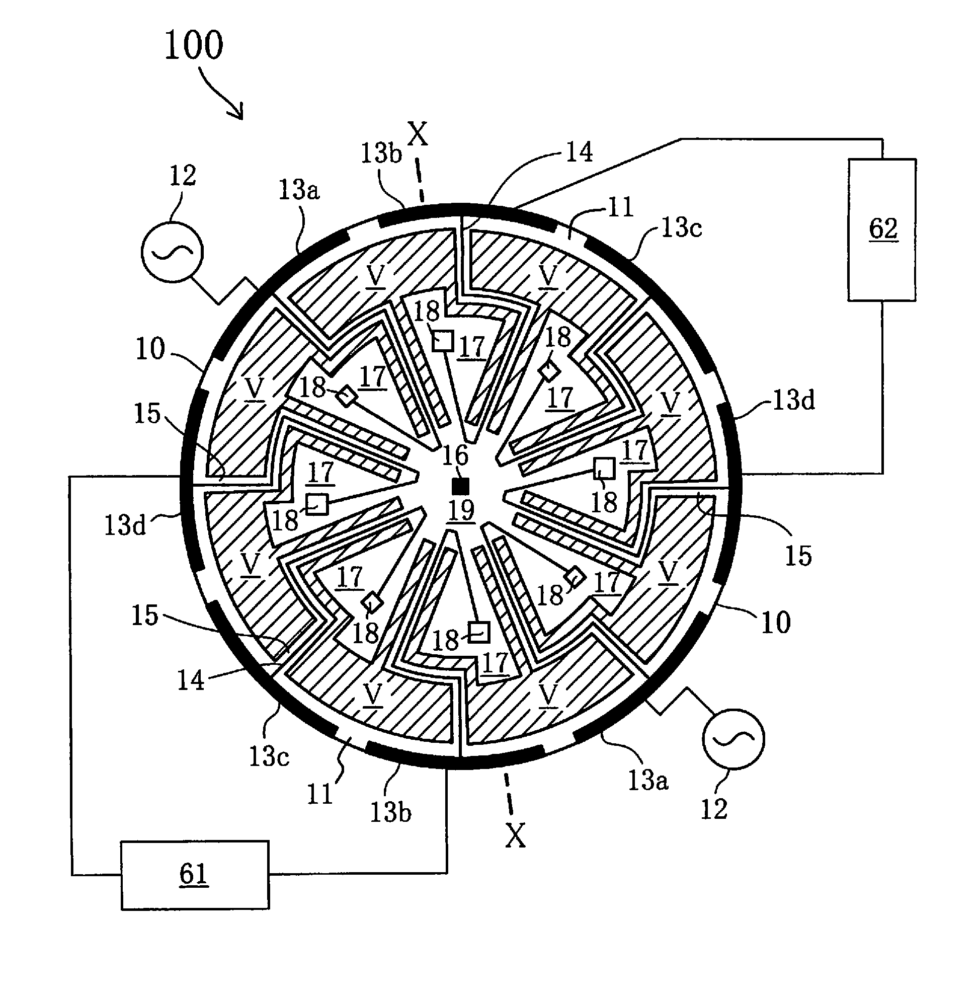
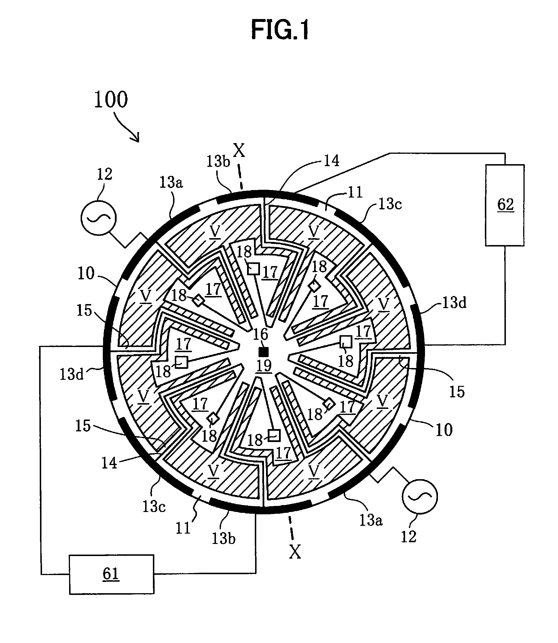
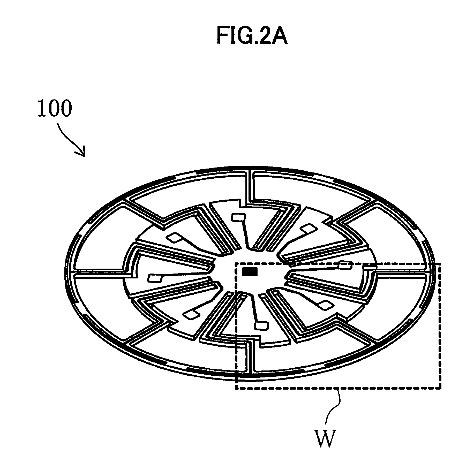
[0075]FIG. 1 is a front view of a structure having a principal function in a ring-shaped vibrating gyroscope 100 according to the present embodiment. FIG. 2A is a perspective view of the structure shown in FIG. 1. FIG. 2B is an enlarged view of a portion (W portion) shown in FIG. 2A. FIG. 3 is a sectional view taken along line X-X of FIG. 1.

[0076]As shown in FIGS. 1 to 3, the ring-shaped vibrating gyroscope 100 according to the present embodiment is generally divided into three areas. A first area includes a ring-shaped vibrating body 11 formed with a silicon substrate 10, a silicon oxide film 20 provided on an upper plane (hereinafter, referred to as an upper surface) of the ring-shaped vibrating body 11, and a plurality of electrodes 13a to 13d formed thereon with a lower-layer metallic film 30, an upper-layer metallic film 50, and a piezoelectric film 40 being sandwiched therebetween. In the present embodiment, the upper-layer metallic film 50 configuring the plurality of electro...

second embodiment

[0098]FIG. 5 is a front view of a structure having a principal function in a different ring-shaped vibrating gyroscope 200 according to the present embodiment. FIG. 6 is a sectional view taken along line Y-Y of FIG. 5. The ring-shaped vibrating gyroscope 200 according to the present embodiment is configured identically with the ring-shaped vibrating gyroscope 100 of the first embodiment, except for the configurations of the piezoelectric film 40 and the upper-layer metallic film 50 in the first embodiment. The manufacturing method therefor is identical with that of the first embodiment except for some steps. Further, the vibration mode in the present embodiment is of cos 2θ as in the first embodiment. Accordingly, the description duplicating with that of the first embodiment may not be repeatedly provided. In FIG. 5, the feedback control circuits 61 and 62 of FIG. 1 are not illustrated expediently for the purpose of simplification in appearance of the figure.

[0099]As shown in FIGS. ...

third embodiment

[0105]FIG. 7 is a front view of a structure having a principal function in a different ring-shaped vibrating gyroscope 300 according to the present embodiment. FIG. 8 is a sectional view taken along line Z-Z of FIG. 7. The ring-shaped vibrating gyroscope 300 according to the present embodiment is configured identically with the ring-shaped vibrating gyroscope 100 of the first embodiment, except for the location of the upper-layer metallic film 50 in the first area in the first embodiment. The manufacturing method therefor is identical with that of the first embodiment except for some steps. Further, the vibration mode in the present embodiment is of cos 2θ as in the first embodiment. Accordingly, the description duplicating with that of the first embodiment may not be repeatedly provided. In FIG. 7 also, the feedback control circuits 61 and 62 of FIG. 1 are not illustrated expediently for the purpose of simplification in appearance of the figure.

[0106]As shown in FIGS. 7 and 8, the ...


PUM


Abstract

A vibratory gyro which is provided with a ring-shaped vibrating body, leg portions flexibly supporting the ring-shaped vibrating body, a plurality of electrodes formed by having a piezoelectric film sandwiched between an upper-layer metallic film and a lower-layer metallic film in the thickness direction, and a fixed potential electrode. The plurality of electrodes include a bank of driving electrodes for exciting primary vibration, detection electrodes for detecting secondary vibration, and suppression electrodes for suppressing the secondary vibration on the basis of a voltage signal from the detection electrodes. The driving electrodes, the detection electrodes and the suppression electrodes are disposed in the region from an outer peripheral edge of the ring-shaped vibrating body to a vicinity of the outer peripheral edge and / or a region from an inner peripheral edge thereof to a vicinity of the inner peripheral edge.

Description

TECHNICAL FIELD[0001]The present invention relates to a vibrating gyroscope including a piezoelectric film and a method for manufacturing the vibrating gyroscope.BACKGROUND ART[0002]In recent years, there have been intensely developed vibrating gyroscopes including a piezoelectric material, in other words, gyroscopes utilizing vibrations, or angular velocity sensors. Conventionally developed is a gyroscope that includes a vibrating body itself made of a piezoelectric material, as disclosed in Patent Document 1. There is also a gyroscope that includes a piezoelectric film formed on a vibrating body. For example, Patent Document 2 discloses a technique for, by using a PZT film as a piezoelectric material, exciting a primary vibration of a vibrating body as well as for detecting partial distortion of a gyroscope, which is caused by a coriolis force generated to the vibrating body when an angular velocity is applied to the vibrating body.[0003]Reduction in size of a gyroscope itself is ...

Claims


Application Information

Patent Timeline
Patent Type & Authority Applications(United States)
IPC IPC(8): G01P15/08G01C19/56G01C19/5677G01C19/5684H10N30/00
CPCH01L41/08G01C19/5677
Inventor ARAKI, RYUTAIKEDA, TAKASHINISHIDA, HIROSHIMORIGUCHI, TAKAFUMIHIRATA, YASUYUKI
Owner SUMITOMO PRECISION PROD CO LTD
Learn More