Electric power transmitting device, electric power receiving device, and power supply method using electric power transmitting and receiving devices

a technology of electric power transmission and receiving device, which is applied in the direction of exchanging data chargers, batteries data exchange, inductance, etc., can solve the problems of increasing the power consumption of the electric power transmitting side, reducing the transmission efficiency, and complicated circuit configuration, so as to reduce power consumption and reduce power consumption. , the effect of fewer components

Inactive Publication Date: 2011-12-22
SEMICON ENERGY LAB CO LTD
View PDF10 Cites 59 Cited by
  • Summary
  • Abstract
  • Description
  • Claims
  • Application Information

AI Technical Summary

Benefits of technology

[0021]According to an embodiment of the present invention, a power supply device can be advantageously provided which has reduced power consumption and transmits electric powe

Problems solved by technology

However, the power transmission has a problem that, when the distance (power transmission distance) is fluctuated between the electric power transmission antenna and the electric power reception antenna, the fluctuation in mutual reactance significantly decreases the transmission efficiency (the ratio of electric power received by the electric power receiving device to electric power supplied by the electric power transmitting device).
In order to supply a certain amount of electric power to the electric power receiving side constantly, the amount of electric power supplied to the electric power transmitting side needs to be increased in response to the decreased transmission efficiency, thereby resulting in an increase in the power

Method used


Image

  • Electric power transmitting device, electric power receiving device, and power supply method using electric power transmitting and receiving devices
  • Electric power transmitting device, electric power receiving device, and power supply method using electric power transmitting and receiving devices
  • Electric power transmitting device, electric power receiving device, and power supply method using electric power transmitting and receiving devices

Examples


embodiment 1

[0038]In the present embodiment, one aspect according to the present invention will be described with reference to FIGS. 1A and 1B, FIGS. 2A and 2B, FIGS. 3A and 3B, FIG. 4, and FIG. 5.

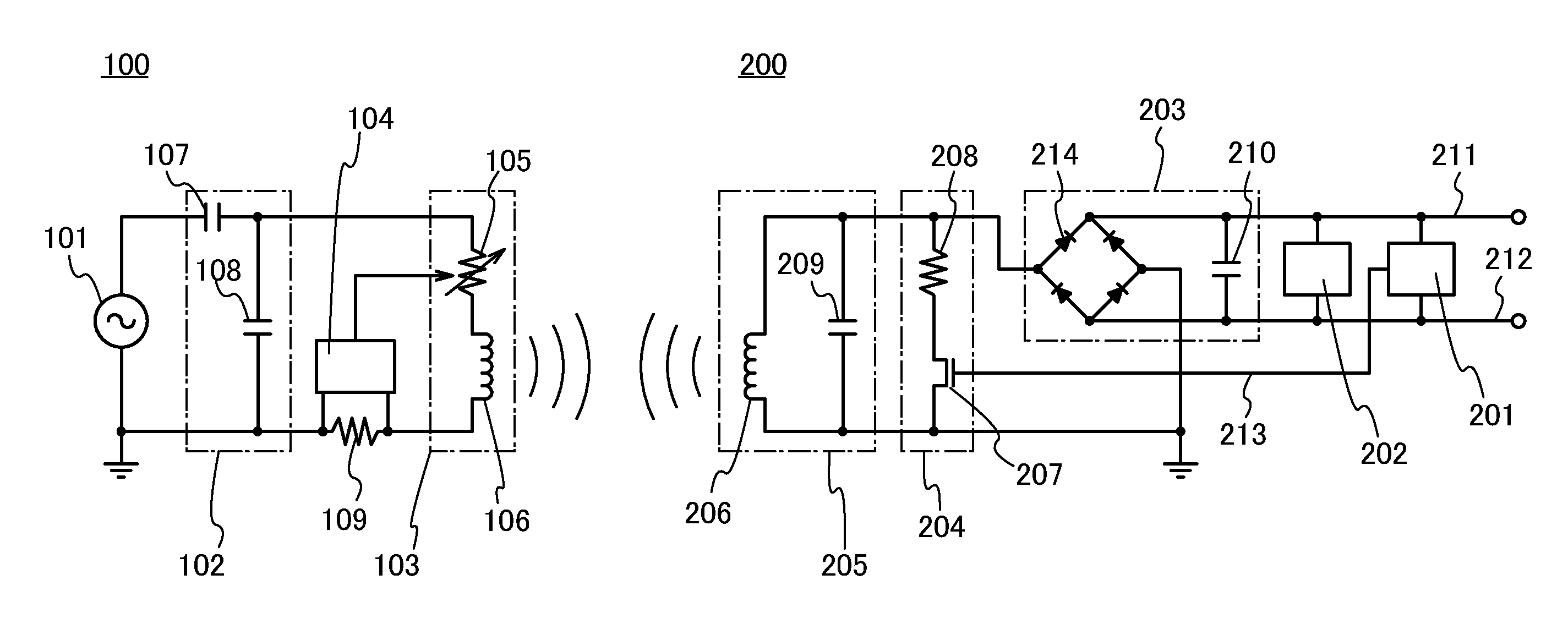
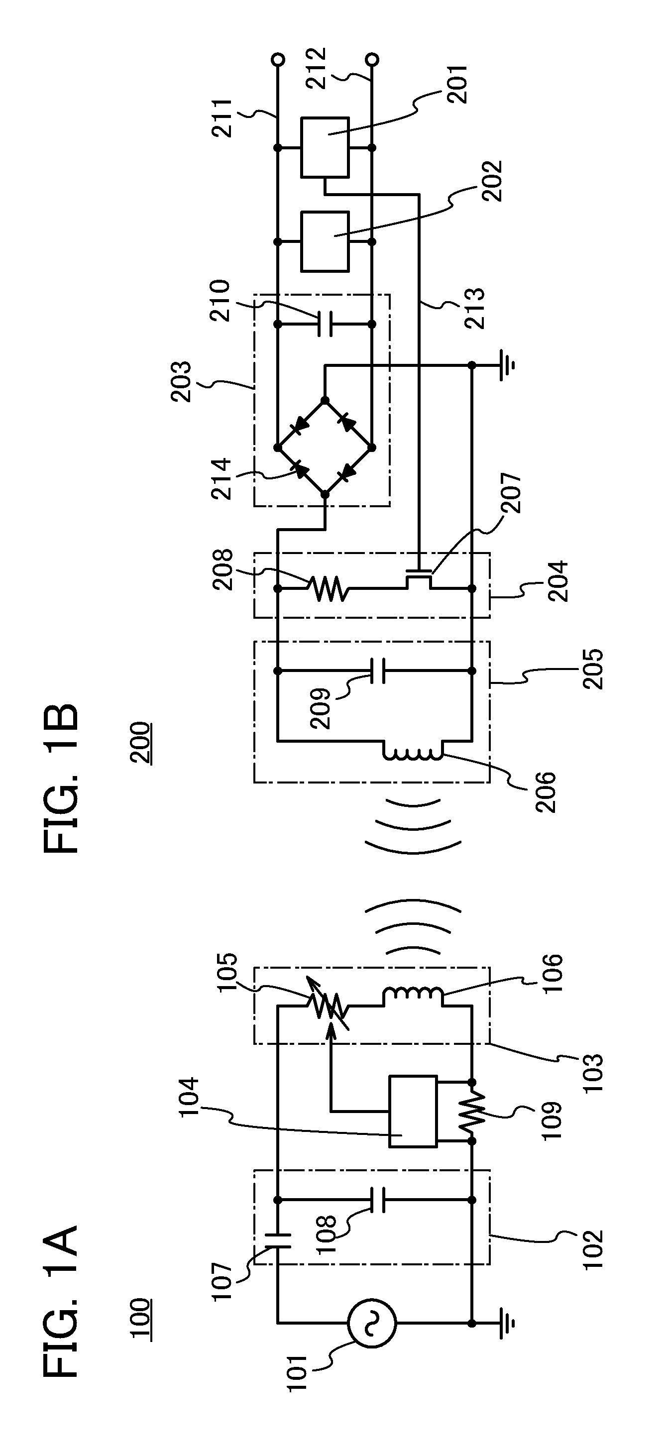
[0039]An electric power transmitting device 100 shown in FIG. 1A includes a power source 101, a matching circuit102, an electric power radiation circuit 103, a modulated signal detection circuit 104, and a resistive element 109. The matching circuit 102 includes a capacitative element 107 connected in series to the power source 101, and a capacitative element 108 connected in parallel to the power source 101.

[0040]The power source 101 generates alternating-current power, and supplies the alternating-current power through the matching circuit 102 to the electric power radiation circuit 103. The frequency fG of the alternating-current power supplied by the power source 101 is not limited to a specific frequency, and for example, any of the following frequencies can be used: 300 GHz to 3THz as frequencie...

embodiment 2

[0070]In the present embodiment, power supply through the electric power transmitting device 100 described in Embodiment 1, and an example of a method for adjusting the Q value of the electric power transmitting device 100 will be described with reference to a flowchart in FIG. 6.

[0071]First, the resistance value of the variable resistive element 105 included in the electric power transmitting device 100 is set to a minimum value so that the Q value is maximized (processing 301). Next, power is supplied from the power source 101 to the electric power radiation circuit 103 to start electric power transmission (processing 302). Next, the modulated signal detection circuit 104 detects the presence or absence of a response signal from the electric power receiving device 200 (determination 303). If no response signal is detected, the electric power transmission is stopped because there is a high possibility that the electric power receiving device 200 is not present, or receives no elect...

embodiment 3

[0079]Examples of moving objects according to one embodiment of the present invention include moving means driven by an electric motor using electric power accumulated in a secondary battery, such as automobiles (automatic two-wheeled vehicles, three or more-wheeled automobiles), motorized bicycles including motor-assisted bicycles, aircrafts, ships, and railroad cars.

[0080]FIG. 8A shows a configuration of a motor boat 8301 as one of moving objects according to the present invention. FIG. 8A illustrates, as an example, a case of the motor boat 8301 including in its hull an electric power receiving device 8302. An electric power transmitting device 8303 for charging the motor boat 8301 can be provided, for example, at mooring facilities for mooring ships in a harbor. Furthermore, the motor boat 8301 can be charged during the moorage of the motor boat 8301.

[0081]The use of the configuration disclosed in the embodiment described above allows electric power to be supplied efficiently, e...


PUM


Abstract

In electric power supply through wireless signals, electric power is supplied efficiently, even when distance fluctuation is caused between an electric power transmitting device and an electric power receiving device. Even when distance fluctuation is caused between the electric power transmitting device for supplying electric power with the use of wireless signals and the electric power receiving device for receiving electric power supplied from the electric power transmitting device, the Q value of the electric power transmitting device is adjusted to optimize the transmission efficiency. The impedance of a resonance circuit of the electric power transmitting device is fluctuated at a constant frequency, the resulting reflected wave is detected as a response signal by the electric power transmitting device, and the Q value of the electric power transmitting device is adjusted to optimize the transmission efficiency.

Description

BACKGROUND OF THE INVENTION[0001]1. Field of the Invention[0002]The present invention relates to an electric power transmitting device for supplying electric power through a wireless signal, an electric power receiving device, and a method for supplying electric power using the electric power transmitting device and the electric power receiving device.[0003]In this specification, the semiconductor device refers to all types of devices which can function by utilizing semiconductor characteristics, and image capturing devices, display devices, electro-optical devices, electric power transmission devices, electric power receiving devices, semiconductor circuits, electronic devices, etc. are all categorized into semiconductor devices.[0004]2. Description of the Related Art[0005]In recent years, with the development of information communication technology, the realization of a ubiquitous society has been proposed in which a variety of electronic devices is connected to a computer network...

Claims


Application Information

Patent Timeline
IPC IPC(8): H01F38/14
CPCH02J5/005H04B5/0093H04B5/0037H02J50/90H02J50/12H02J50/40H02J7/00034H02J7/00
Inventor KAMATA, KOICHIRO
Owner SEMICON ENERGY LAB CO LTD
Why Eureka
Try Eureka