LED lamp and a heat sink thereof having a wound heat pipe

a heat sink and led lamp technology, applied in the field of illumination devices, can solve the problems of short life of tungsten lamps, increased maintenance costs, and insufficient heat dissipation effect, and achieve strong and rapid heat dissipation effect, good heat dissipation effect, and greater heat dissipation effect.

Active Publication Date: 2011-12-22
KITAGAWA HLDG
View PDF3 Cites 49 Cited by
  • Summary
  • Abstract
  • Description
  • Claims
  • Application Information

AI Technical Summary

Benefits of technology

[0024]The heat-dissipating fins are arranged radially around the LED module, so that the heat-dissipating fins act as a lamp shroud with a good heat-dissipating effect.
[0025]Since the heat pipe has a strong and rapid heat-conducting effect, the heat generated by the LED module can be rapidly conducted by the wound heat pipe to the heat-conducting base and the whole region of the respective heat-dissipating fins. Thus, the heat will not be accumulated in a partial region of the heat-dissipating fins, and the heat-conducting path can be shortened to accelerate the heat-conducting speed. Furthermore, the heat can be distributed uniformly on the respective heat-dissipating fins to utilize the whole area of the heat-d

Problems solved by technology

However, the tungsten filament is prone to be blown and thus the lifetime of the tungsten lamp is short.
However, such a heat-dissipating effect is insufficient.
If the heat is not dissipated immediately, the heat will be accumulated in the LED module to deteriorate the lifetime of the LED lamp and thus increase the maintenance cost.
Thus, th

Method used


Image

  • LED lamp and a heat sink thereof having a wound heat pipe
  • LED lamp and a heat sink thereof having a wound heat pipe
  • LED lamp and a heat sink thereof having a wound heat pipe

Examples


Embodiment Construction

[0034]The detailed description and technical contents of the present invention will become apparent with the following detailed description accompanied with related drawings. It is noteworthy to point out that the drawings is provided for the illustration purpose only, but not intended for limiting the scope of the present invention.

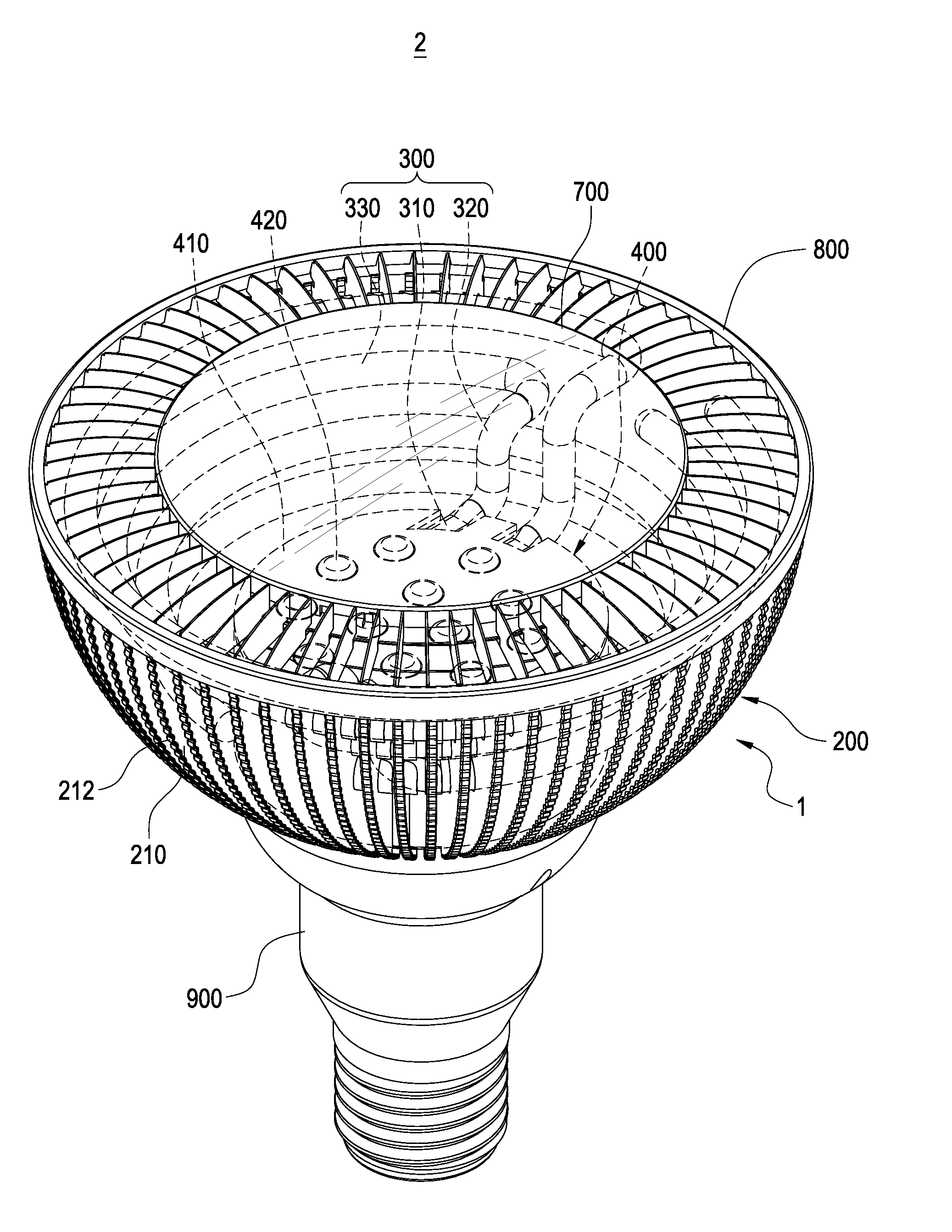
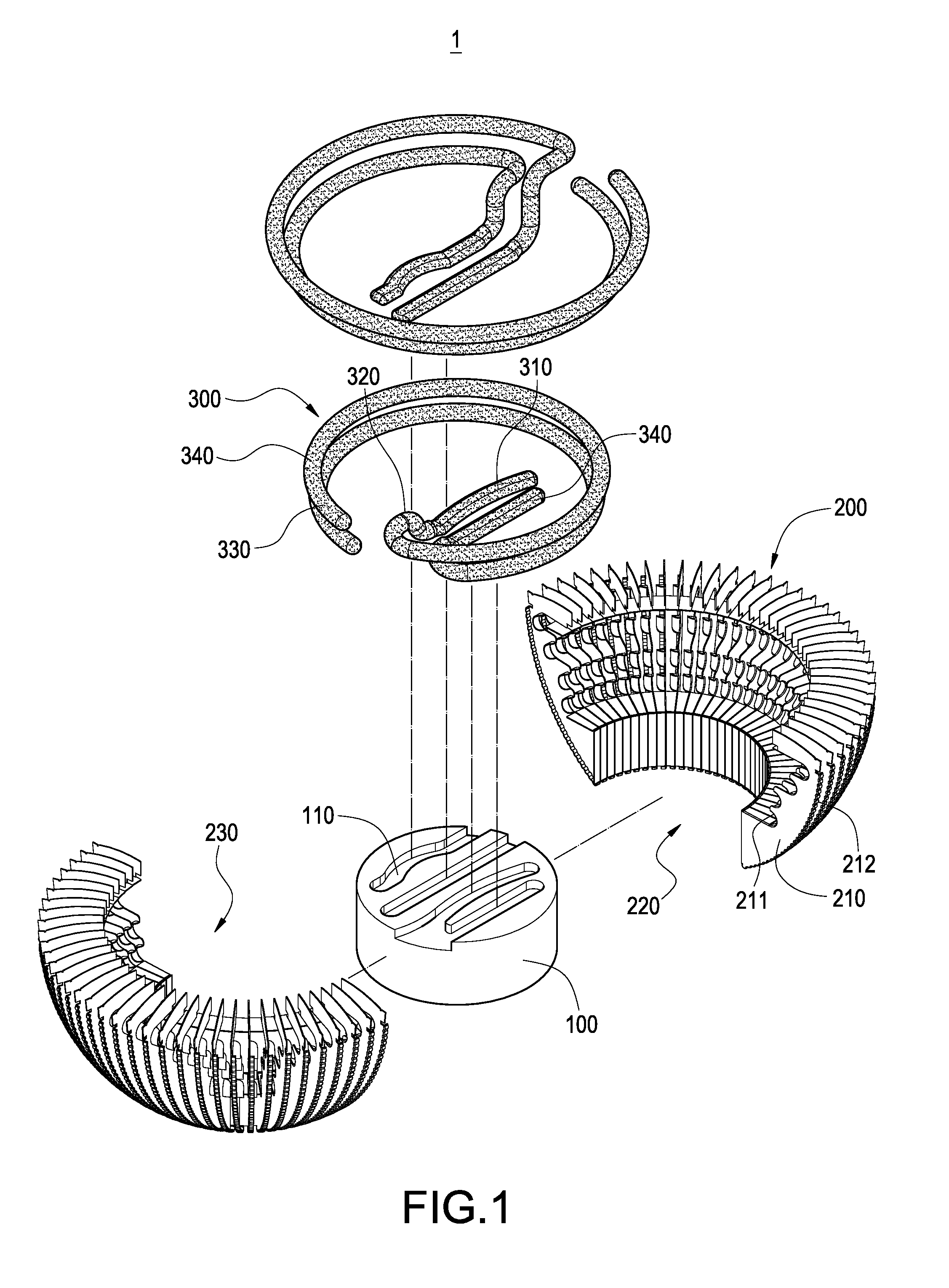
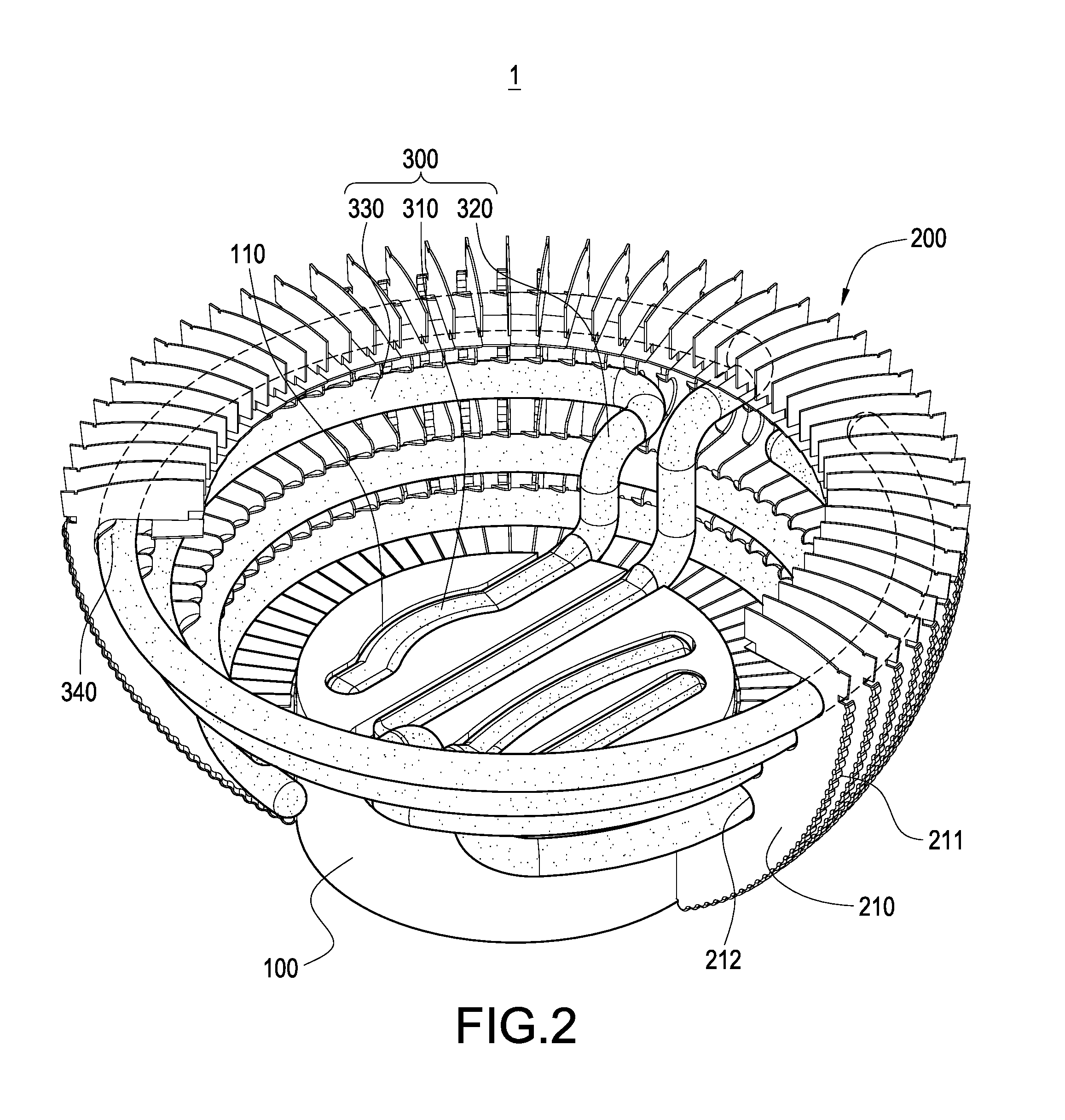
[0035]The present invention relates to a heat sink having a wound heat pipe. Please refer to FIGS. 1 to 3. The heat sink 1 includes a heat-conducting base 100, a heat-dissipating fin set 200, and at least one wound heat pipe 300.

[0036]The heat-conducting base 100 is made of materials having good heat conductivity and may be made of metals including but not limited to copper, aluminum or the like. One side of the heat-conducting base 100 is provided with an insertion slot 110 and the other side thereof is provided with a connecting trough 120.

[0037]The heat-dissipating fin set 200 comprises a plurality of heat-dissipating fins 210 arranged radially at int...


PUM


Abstract

The present invention relates to a LED lamp and a heat sink thereof having a wound heat pipe. The LED lamp includes the heat sink, a LED module and a lamp base electrically connected to the LED module. The heat sink includes a heat-conducting base, a heat-dissipating fin set and a wound heat pipe. The heat-dissipating fin set includes a plurality of heat-dissipating fins arranged at the outer periphery of the heat-conducting base. The heat-dissipating fins form an accommodating space. The wound heat pipe includes an evaporating section brought into thermal contact with the heat-conducting base and a condensing section brought into thermal contact with the heat-dissipating fins. The LED module abuts against the heat-conducting base and the evaporating section. By this structure, the heat-conducting path is shortened, the heat-conducting speed is accelerated, and the heat is rapidly and uniformly distributed to the heat-dissipating fins to improve the heat-dissipating efficiency.

Description

BACKGROUND OF THE INVENTION[0001]1. Field of the Invention[0002]The present invention relates to an illuminating device, in particular to a LED lamp and a heat sink having a wound heat pipe.[0003]2. Description of Prior Art[0004]Illuminating devices are very important tools in the civilization of human beings, by means of which people can recognize their locations even in a dark environment. Tungsten lamps are one kind of illuminating devices, in which a tungsten filament is used as a light-emitting source. Thus, the tungsten lamp has a simple structure. When an electric current passes through the tungsten filament, it can be heated to emit light, so that the tungsten lamp can be used for illumination. However, the tungsten filament is prone to be blown and thus the lifetime of the tungsten lamp is short.[0005]With the advancement of science and technology, LED lamps are developed. Light emitting diode (LED) is a solid light source capable of converting electricity into light energy...

Claims


Application Information

Patent Timeline
IPC IPC(8): H01J61/52F28D15/04
CPCF21V29/004F21V29/006F21Y2101/02F21K9/137F21V29/78F28D15/0275F21V29/20F21V29/773F21K9/1375F21K9/23F21K9/233F21Y2115/10F21V29/51
Inventor LIN, KUO-LENLIN, CHEN-HSIANGCHENG, CHIH-HUNG
Owner KITAGAWA HLDG
Why Eureka
Try Eureka