Power control device for LED lighting and lighting system

a technology of power control device and led lighting, which is applied in the direction of lighting apparatus, light sources, instruments, etc., can solve the problems of long work time, complicated wiring installation, and high power consumption

Inactive Publication Date: 2011-12-22
MITSUMI ELECTRIC CO LTD
View PDF0 Cites 40 Cited by
  • Summary
  • Abstract
  • Description
  • Claims
  • Application Information

AI Technical Summary

Benefits of technology

As described above, the present invention brings about an effect of allowing light control of a plurality of LED lamps to be performed merely

Problems solved by technology

Recently, in order to reduce carbon dioxide emissions, LED lighting, which has low power consumption, is spreading instead of an incandescent lamp, which has high power consumption.
Thus, the more the number of LED lamps to be installed increases along with enlargement of the building, the more the number and length of wires increase, which causes probl

Method used


Image

  • Power control device for LED lighting and lighting system
  • Power control device for LED lighting and lighting system
  • Power control device for LED lighting and lighting system

Examples


first embodiment

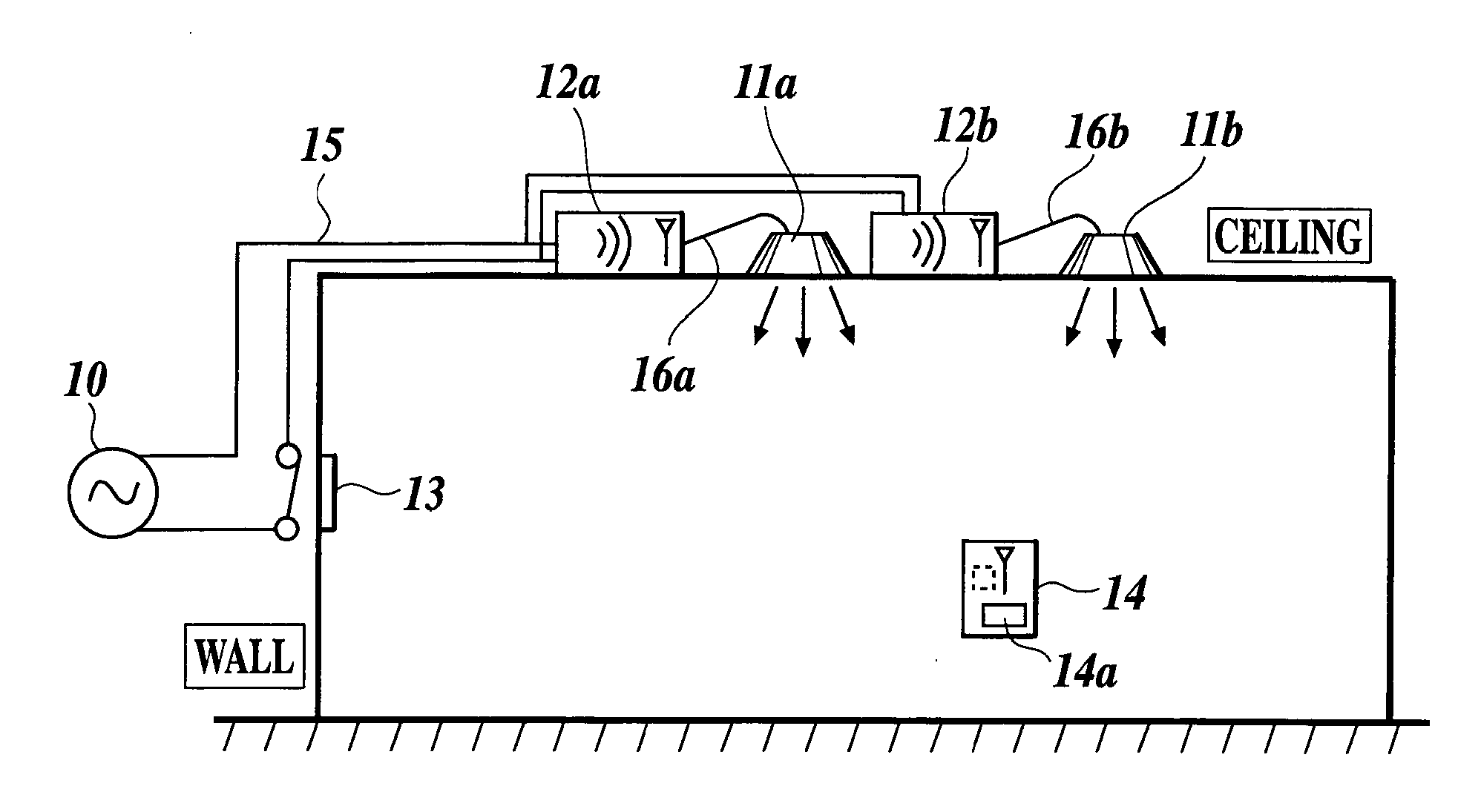
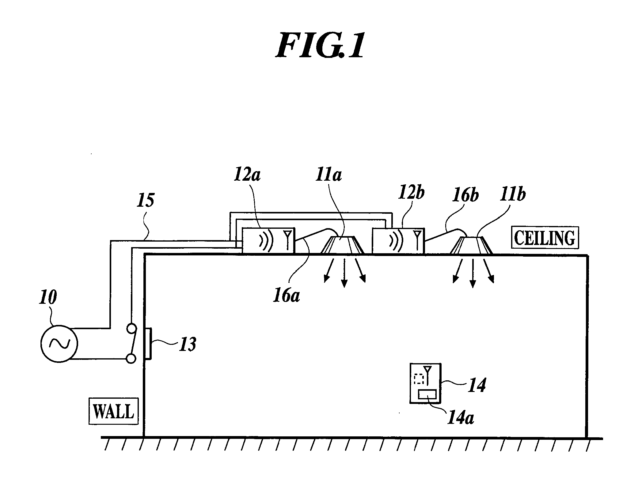
FIG. 1 shows a first embodiment of a lighting system according to the present invention in which a plurality of LED lamps are used and controlled by a wireless switch.

A lighting system of the present embodiment includes LED lamps 11a, 11b . . . as lighting fixtures attached to the ceiling of a building to be directed downward, LED power units 12a, 12b . . . each provided for each lamp to supply power to it, a main power switch 13 to turn on and off the power of the entire lighting system, and a wireless switch 14 transmitting a wireless signal for light control to the LED power units 12a, 12b . . . , and power wiring 15 supplying AC power supply voltage from a common AC power supply 10 to the LED power units 12a, 12b . . . is installed behind the ceiling from the inside of the wall of the building, as shown in FIG. 1. The LED power units 12a, 12b . . . and the corresponding LED lamps 11a, 11b . . . are connected via cables 16a, 16b . . . .

The wireless switch 14 is a kind of remote ...

second embodiment

Next, a second embodiment of the lighting system according to the present invention will be described.

The lighting system of the second embodiment is configured to be capable of performing light control by using a plurality of wireless switches each transmitting a unique ID code (identification code). For brightness control, the first control method (refer to FIG. 3) described in the above first embodiment is applied. FIG. 7 shows an example of the lighting system of the second embodiment.

As shown in FIG. 7, in the lighting system of the present embodiment, a space is divided into 4 areas A, B, C, and D and is provided with 36 LED lamps 11 in total with each area provided with 9 lamps, in the same manner as that of the lighting system in FIG. 5A. The lighting system of the present embodiment differs with the embodiment in FIG. 5 in that wireless switches 14A, 14B, 14C, 14D, corresponding to the respective areas A, B, C, D, each transmitting a unique ID code are provided so that ligh...

modification example

FIG. 8 shows a modification example of the lighting system of the second embodiment.

In this modification example, a common wireless switch 14E having a unique ID code is further added to the lighting system in FIG. 7, and each of the LED power units corresponding to each LED lamp 11 has stored therein the ID code of the common wireless switch 14E as well as the ID code of the corresponding wireless switch. Each LED power unit is configured to turn on or off the corresponding LED lamp when it receives the ID code of the common wireless switch 14E. Accordingly, in the lighting system of this modification example, when the user operates the common wireless switch 14E, the LED lamps in all areas A, B, C, D are controlled to be turned on or off at a time.

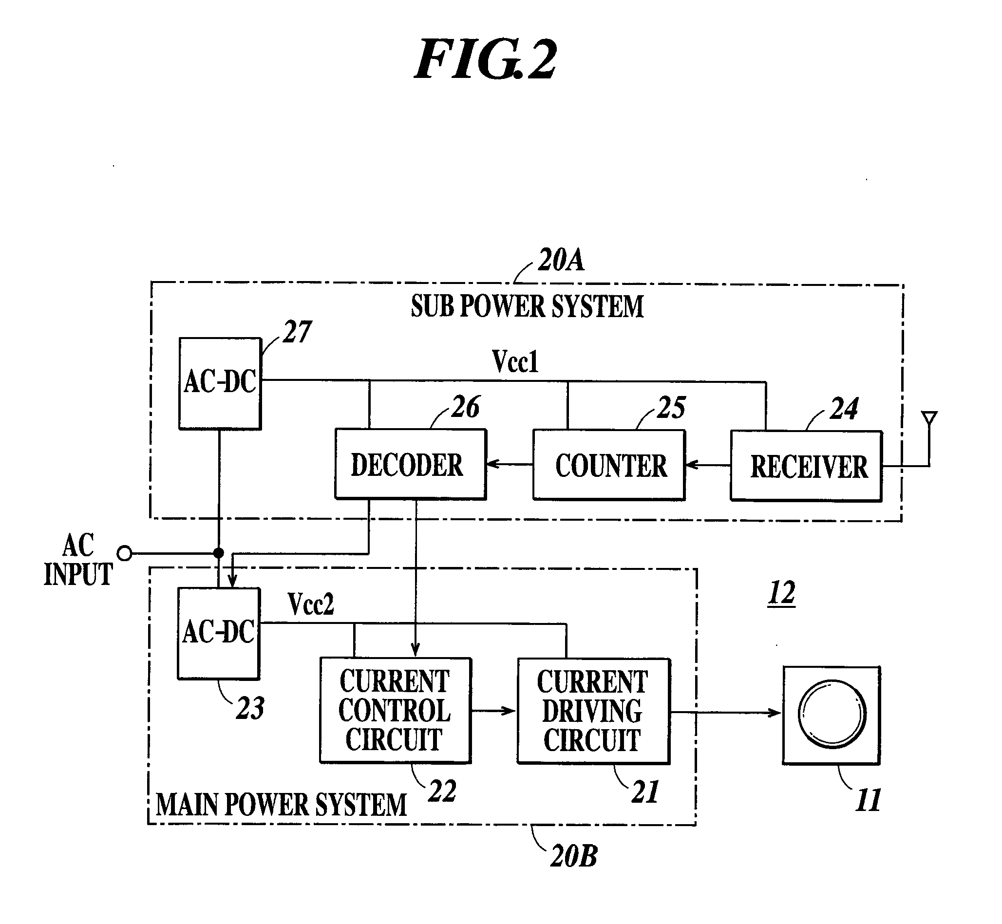
In the lighting system as the modification example, it is preferable to provide the receiver 24 (refer to FIG. 2) of each LED power unit with a transmission function so that the receiver 24 may transmit a received signal to the receivers...


PUM


Abstract

A lighting system including a power control device for controlling illuminance of a lighting fixture by outputting current to drive the lighting fixture and controlling the current, a plurality of lighting fixtures each driven to be lit by the power control device, and a switch device incorporating an energy self-supplying unit converting an operating force of a switch button into electric energy. The power control device includes a first circuit section having a receiver for receiving a wireless signal having a predetermined frequency and a control signal generating circuit for generating a control signal according to the number of times of reception of the wireless signal and operated by a first power system and a second circuit section operated by a second power system and outputting current according to the control signal from the first circuit section, and the second power system is not operated when not outputting current.

Description

BACKGROUND OF THE INVENTION1. Field of the InventionThe present invention relates to a power control device for a lighting fixture, that is, a power control device for turning on / off and light control of LED lighting, and more specifically relates to a power control device for LED lighting using a wireless switch that does not require a battery and a lighting system using the same.2. Description of the Related ArtRecently, in order to reduce carbon dioxide emissions, LED lighting, which has low power consumption, is spreading instead of an incandescent lamp, which has high power consumption. Also, a technique of controlling light in an LED lighting apparatus has been proposed (e.g., refer to Japanese Patent Application Laid-Open publication No. 2009-301876).There is a case in which a plurality of LED lighting fixtures (each hereinafter referred to as an LED lamp) are installed with a predetermined distance on a ceiling of a relatively large building. To construct a lighting system t...

Claims


Application Information

Patent Timeline
IPC IPC(8): H05B37/02
CPCH05B37/0272H05B47/19
Inventor KUROKI, TAISUKEKATAYAMA, TAKAYUKIKOMAGATA, MASAAKISUGIE, NOBORUSUZUKI, TAKESHI
Owner MITSUMI ELECTRIC CO LTD
Why Eureka
Try Eureka