Cell for fuel cell and fuel cell
- Summary
- Abstract
- Description
- Claims
- Application Information
AI Technical Summary
Benefits of technology
Problems solved by technology
Method used
Image

Examples
first embodiment
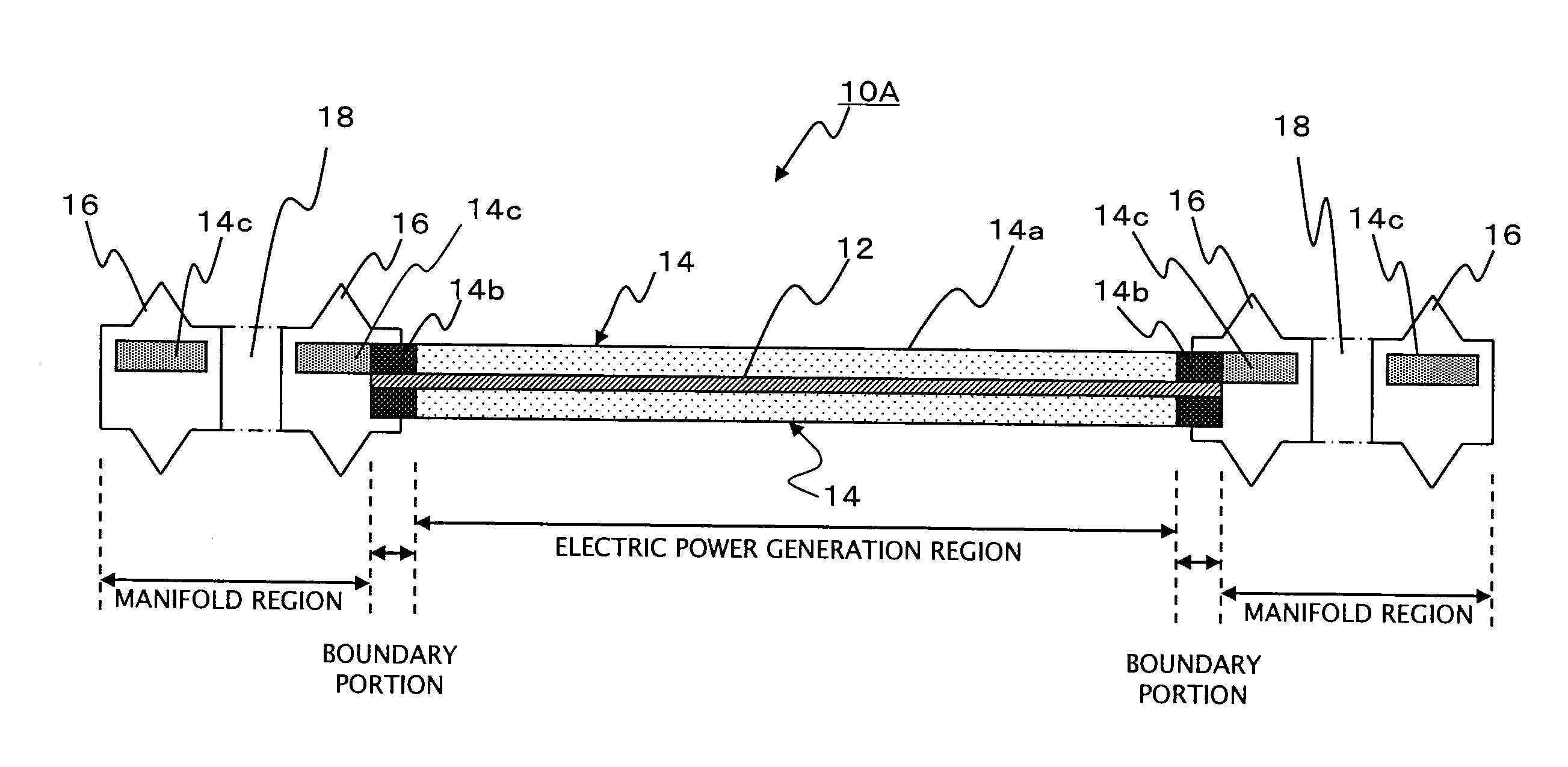
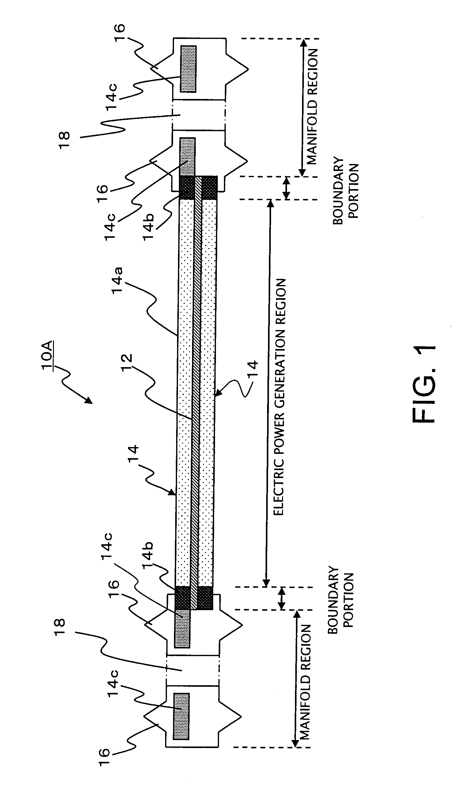
[0065]As illustrated in FIG. 1, a cell for a fuel cell (hereafter also referred to as a “unit cell”) according to the present embodiment comprises a membrane electrode assembly 10A, composed of an assembly 12 having a fuel electrode and an air electrode on an electrolyte membrane, and first and second gas diffusion layers 14 that supply a fuel gas and an oxidizing gas to the fuel electrode and air electrode respectively of the assembly 12, wherein the membrane electrode assembly 10A is sandwiched between a pair of separators (not shown in the figure) described below. In this embodiment, the gas diffusion layers represent the first and second gas diffusion members of the present invention.
[0066]Moreover, the cell for a fuel cell according to the present embodiment includes an electric power generation region capable of generating electric power in which the assembly 12 and the first and second gas diffusion layers 14 are laminated together, and a manifold region, which is provided at...
second embodiment
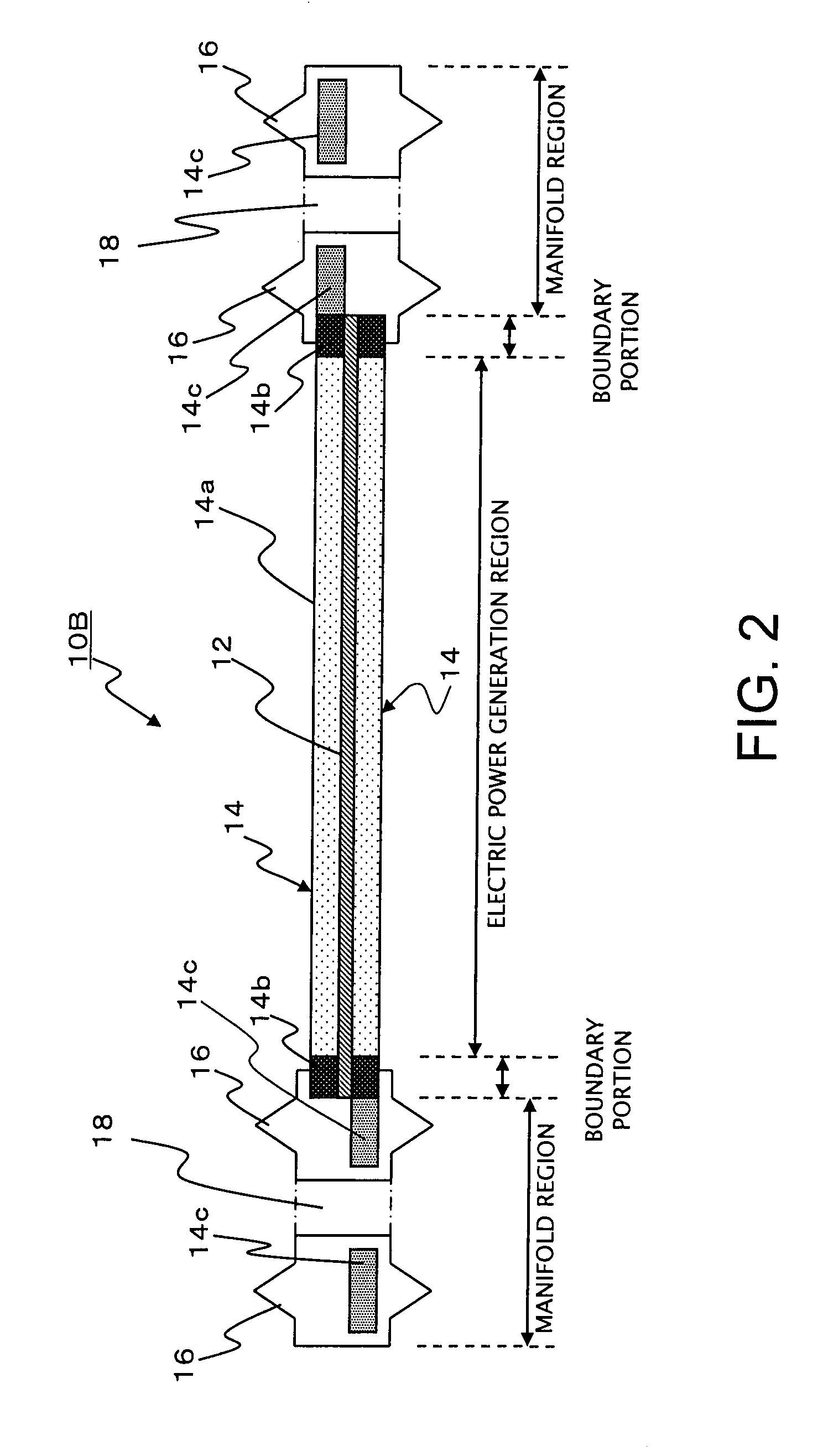
[0073]FIG. 2 illustrates the structure of a membrane electrode assembly 10B of a cell for a fuel cell according to a second embodiment. The structure of this membrane electrode assembly 10B of the second embodiment is the same as that of the membrane electrode assembly 10A of the first embodiment illustrated in FIG. 1, with the exception that whereas in the membrane electrode assembly 10A of the first embodiment, only the end portions of one of the gas diffusion layers 14 were extended into the manifold region, in the membrane electrode assembly 10B of the second embodiment, one end portion of both the first and second gas diffusion layers 14 extends into the manifold region, and the peripheral edge portions 14c of the first and second gas diffusion layers 14 are formed so as not to overlap.
[0074]In the first and second embodiments, the extended peripheral edge portions 14c of the first and second gas diffusion layers 14 are formed so as not to overlap, but in those cases where the ...
third embodiment
[0075]FIG. 3 illustrates the structure of a membrane electrode assembly 10C of a cell for a fuel cell according to a third embodiment. The structure of this membrane electrode assembly 10C of the third embodiment is the same as that of the membrane electrode assembly 10A of the first embodiment illustrated in FIG. 1, with the exception that whereas in the membrane electrode assembly 10A of the first embodiment, the end portions of the assembly 12 only extended beyond the electric power generation region as far as the boundary portions, in the membrane electrode assembly 100 of the third embodiment, both end portions of the assembly 12 extend beyond the respective boundary portion and into the manifold region.
PUM
| Property | Measurement | Unit |
|---|---|---|
| Pore size | aaaaa | aaaaa |
| Thickness | aaaaa | aaaaa |
| Porosity | aaaaa | aaaaa |
Abstract
Description
Claims
Application Information
 - R&D
- Intellectual Property
- Life Sciences
- Materials
- Tech Scout
- Unparalleled Data Quality
- Higher Quality Content
- 60% Fewer Hallucinations
Browse by: Latest US Patents, China's latest patents, Technical Efficacy Thesaurus, Application Domain, Technology Topic, Popular Technical Reports.
© 2025 PatSnap. All rights reserved.Legal|Privacy policy|Modern Slavery Act Transparency Statement|Sitemap|About US| Contact US: help@patsnap.com