Exhaust gas recirculation device of engine

a technology of exhaust gas recirculation and engine, which is applied in the direction of machines/engines, mechanical devices, and non-fuel substance addition to fuel, etc., can solve the problems of improperly large devices, excessive temperature rise, and improper amount of fresh intake air flowing into cylinders

Inactive Publication Date: 2011-12-29
MAZDA MOTOR CORP
View PDF48 Cites 34 Cited by
  • Summary
  • Abstract
  • Description
  • Claims
  • Application Information

AI Technical Summary

Benefits of technology

[0006]According to the present invention, the two branch passages branching from the exhaust passage are formed inside the cylinder head, the respective opening portions of the two branch passages are formed at the rear end face of the cylinder head, and the EGR cooler and the bypass pipe are directly attached to the cylinder head. Accordingly, respective pipes to supply the exhaust gas from the exhaust passage to the EGR cooler and the bypass pipe are provided outside the cylinder head, so that the size of the device can be made smaller, compared to a case in which the EGR cooler and the bypass pipe are attached to the respective pipes outside the cylinder head. Further, attachment of the EGR cooler and the bypass pipe can be easier.
[0007]According to an embodiment of the present invention, the opening portion of the branch passage connecting to the EGR cooler is formed at a position which is further away from the intake system of the engine body, compared to the opening portion of the branch passage connecting to the bypass pipe. Thereby, the distance from the opening portion connecting to the EGR cooler to the intake system can be properly long and thus the sufficiently-large volume of the EGR cooler provided between these can be ensured. The sufficiently-large volume of the EGR cooler can provide the sufficient heat-exchanging amount of the EGR cooler as well, so that the EGR gas can be cooled properly. Further, the distance from the opening portion connecting to the bypass pipe to the intake system can be properly short and thus the distance between the bypass pipe and the intake system can be properly short. This arrangement can suppress the amount of radiation of heat of the EGR gas flowing down through the bypass pipe to the intake system, so that the high-temperature EGR gas can be surely recirculated to the intake system.
[0008]According to another embodiment of the present invention, the EGR cooler extends in an engine-body width direction from a vicinity of the opening portion of the branch passage connecting to the EGR cooler toward the intake system arranged on one side of the engine body in the engine-body width direction. Thereby, the mount of rearward projection of the EGR cooler can be suppressed to provide compact arrangement of the EGR cooler, ensuring the sufficient heat-exchanging amount of the EGR cooler.
[0009]According to another embodiment of the present invention, the opening portions of the two branch passages are positioned at different levels from each other, and the EGR cooler and the bypass pipe extend in parallel to and vertically away from each other. Thereby, by arranging the EGR cooler and the bypass pipe from the opening portions along the engine-body width direction, the EGR cooler and the bypass pipe can be disposed in parallel to each other, so that the mount of rearward projection of the bypass pipe can be suppressed to be properly small in addition to the EGR cooler.
[0010]According to another embodiment of the present invention, the EGR cooler comprises an EGR cooler body extending in the engine-body width direction, an exhaust introduction portion provided at one end of the EGR cooler body in a longitudinal direction and introducing the exhaust gas into an inside of the EGR cooler body, and an exhaust discharge portion provided at the other end of the EGR cooler body in the longitudinal direction and discharging the exhaust gas inside the EGR cooler body to the intake system, and the exhaust introduction portion is connected to the opening portion. Thereby, the distance between the exhaust discharge portion of the EGR cooler and the intake system can be properly small to shorten the pipe between the EGR cooler and the intake system, ensuring the sufficiently-large heat-exchanging volume of the EGR cooler. This can make the device properly small-sized and simple.
[0011]According to another embodiment of the present invention, the exhaust gas recirculation device further comprises an EGR-gas passage structural portion formed at an intake manifold connected to the engine body, and the EGR cooler and the bypass pipe are supported at the EGR-gas passage structural portion. Thereby, the support rigidity of the device can be ensured and the support structure can be properly simple.

Problems solved by technology

Under the other condition, however, the intake temperature may rise excessively, so that there is a problem in that the amount of fresh intake air flowing into cylinders would decrease improperly.
In this case, however, there is another problem in that the device would become improperly large sized due to providing the EGR cooler and the bypass pipe.

Method used


Image

  • Exhaust gas recirculation device of engine
  • Exhaust gas recirculation device of engine
  • Exhaust gas recirculation device of engine

Examples


Embodiment Construction

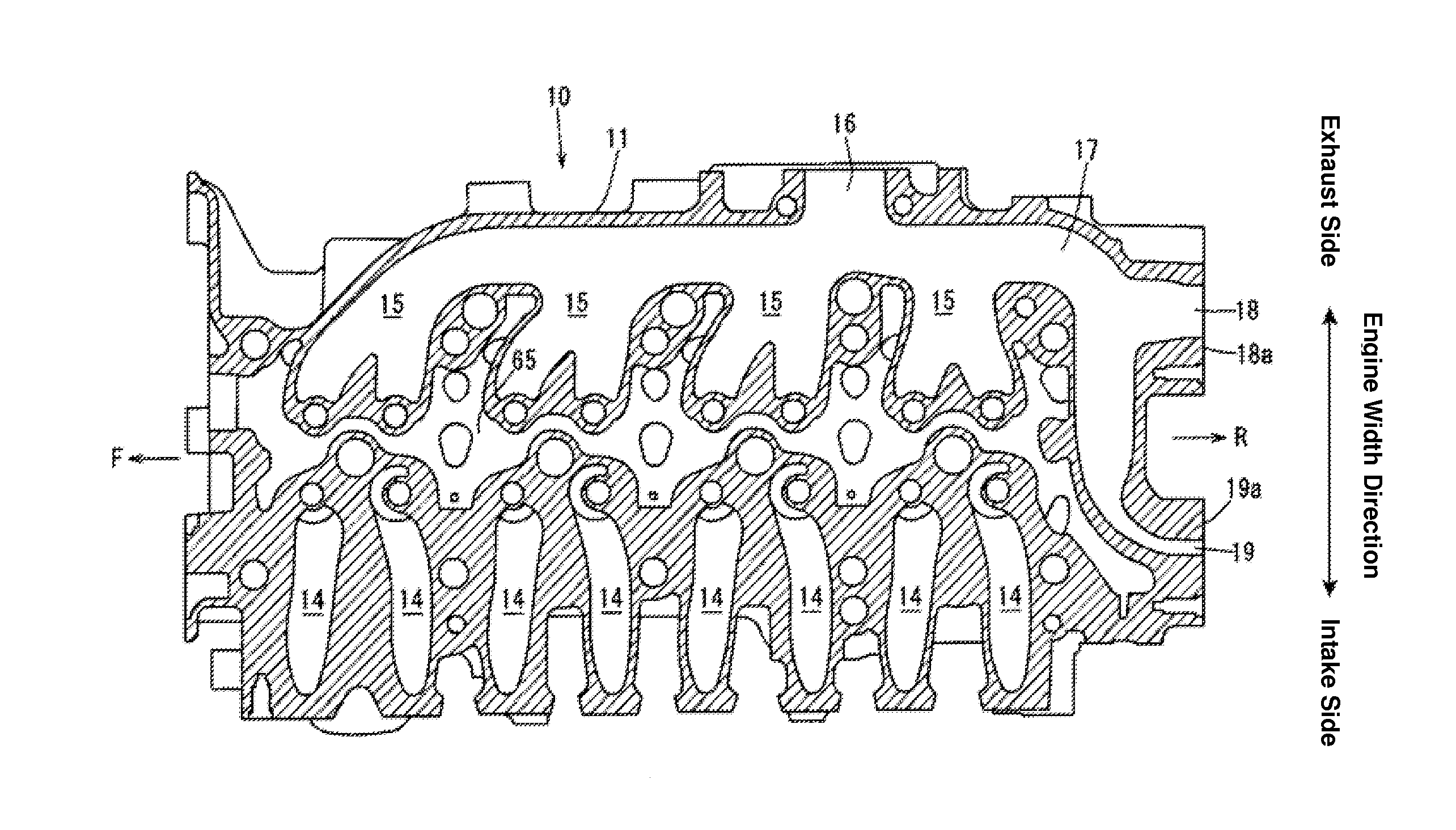
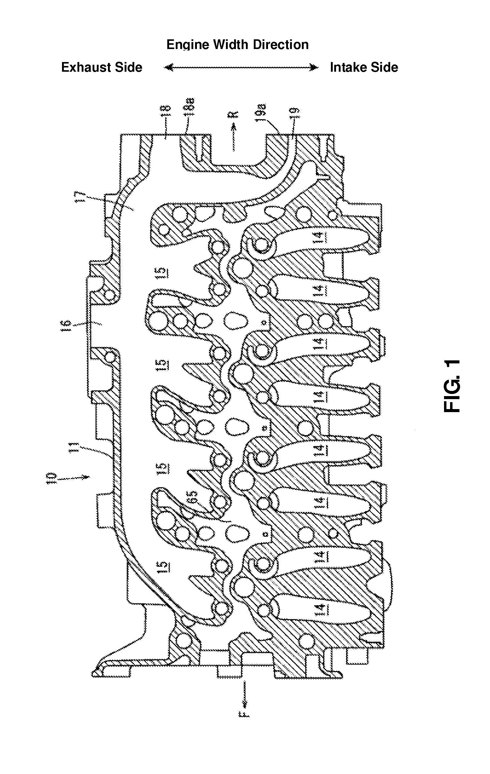
[0027]Hereafter, a preferred embodiment of an exhaust gas recirculation device of an engine according to the present invention will be descried referring to the drawings.

[0028]The exhaust gas recirculation device of an engine is attached to an engine body 10. As shown in FIG. 11 and others, the engine body 10 comprises a cylinder head 11, a cylinder block 46 which is fixed to the cylinder head 11, and a cylinder head cover, not illustrated, which is attached to a specified portion of the cylinder head on the opposite side to the cylinder block 46. Hereafter, the direction of row of the cylinder head 11 and the cylinder block 46 will be referred to as the vertical direction, the side of the cylinder head 11 will be referred to as the upper side, and the side of the cylinder block 46 will be referred to as the lower side.

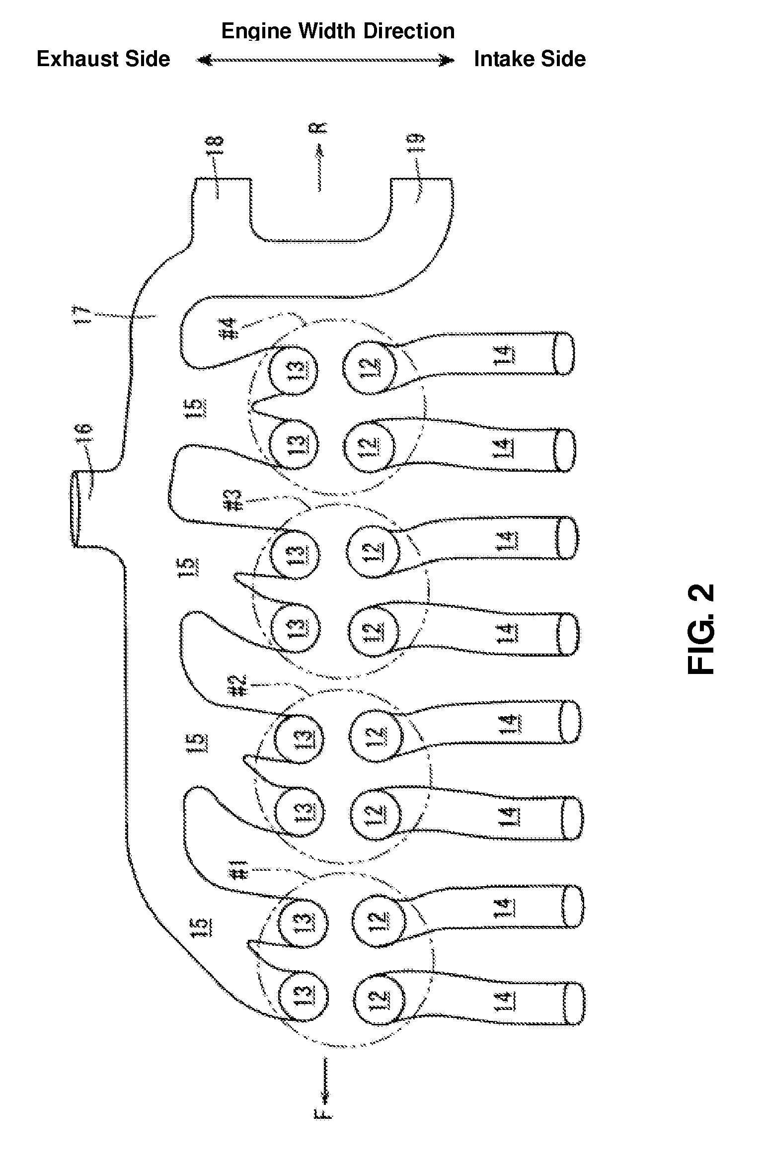
[0029]The exhaust gas recirculation device of an engine according to the present invention recirculates part of exhaust gas discharged from the engine body 10, i.e., ...


PUM


Abstract

A connecting passage is formed inside a cylinder head, which extends rearward from an exhaust passage and connects to the exhaust passage. The connecting passage branches inside the cylinder head into two branch passages, which open at a rear end face of the cylinder head, respectively. An opening portion, one of opening portions of the branch passages, connects to an EGR cooler, and another opening portion, the other of opening portions of the branch passages, connects to a bypass pipe. Accordingly, the exhaust gas recirculation device of an engine which can restrain the device from being improperly large sized, providing the EGR cooler and the bypass pipe, can be provided.

Description

BACKGROUND OF THE INVENTION[0001]The present invention relates to an exhaust gas recirculation device of an engine, which recirculates part of exhaust gas discharged from an exhaust passage provided inside a cylinder head of an engine body having plural cylinders arranged in line in a longitudinal direction to an intake system of the engine body.[0002]Conventionally, it has been done to recirculate part of exhaust gas to an intake system and decrease the temperature of combustion gas with the recirculated EGR gas to reduce an emission of NOx. In general, a device in which part of the exhaust gas is recirculated to the intake system from an exhaust manifold which is connected to a cylinder head outside the cylinder head through an EGR passage provided outside the cylinder head is known as the above-described exhaust gas recirculation device to recirculate part of the exhaust gas, i.e., EGR gas, to the intake system. Further, as disclosed in Japanese Patent Laid-Open Publication No. 2...

Claims


Application Information

Patent Timeline
Patent Type & Authority Applications(United States)
IPC IPC(8): F02M25/07
CPCF02F1/243F02M25/0722F02M25/0728F02M25/0717F02M25/0747F02M25/0715F02M25/0726Y02T10/121F02M26/19F02M26/25F02M26/13F02M26/14F02M26/22F02M26/41Y02T10/12
Inventor KOJIMA, YUJISUNADA, TOMOHIROISHIMOTO, DAIJIRO
Owner MAZDA MOTOR CORP
Why Eureka
Try Eureka