Bi-directional power converter with regulated output and soft switching

a power converter and regulated output technology, applied in power conversion systems, electric variable regulation, instruments, etc., can solve the problems of adversely affecting the ability to achieve high power density and high power conversion efficiency, and significant switching losses, and achieve the effect of loss-less switching

Active Publication Date: 2011-12-29
GREECON TECH
View PDF6 Cites 91 Cited by
  • Summary
  • Abstract
  • Description
  • Claims
  • Application Information

AI Technical Summary

Benefits of technology

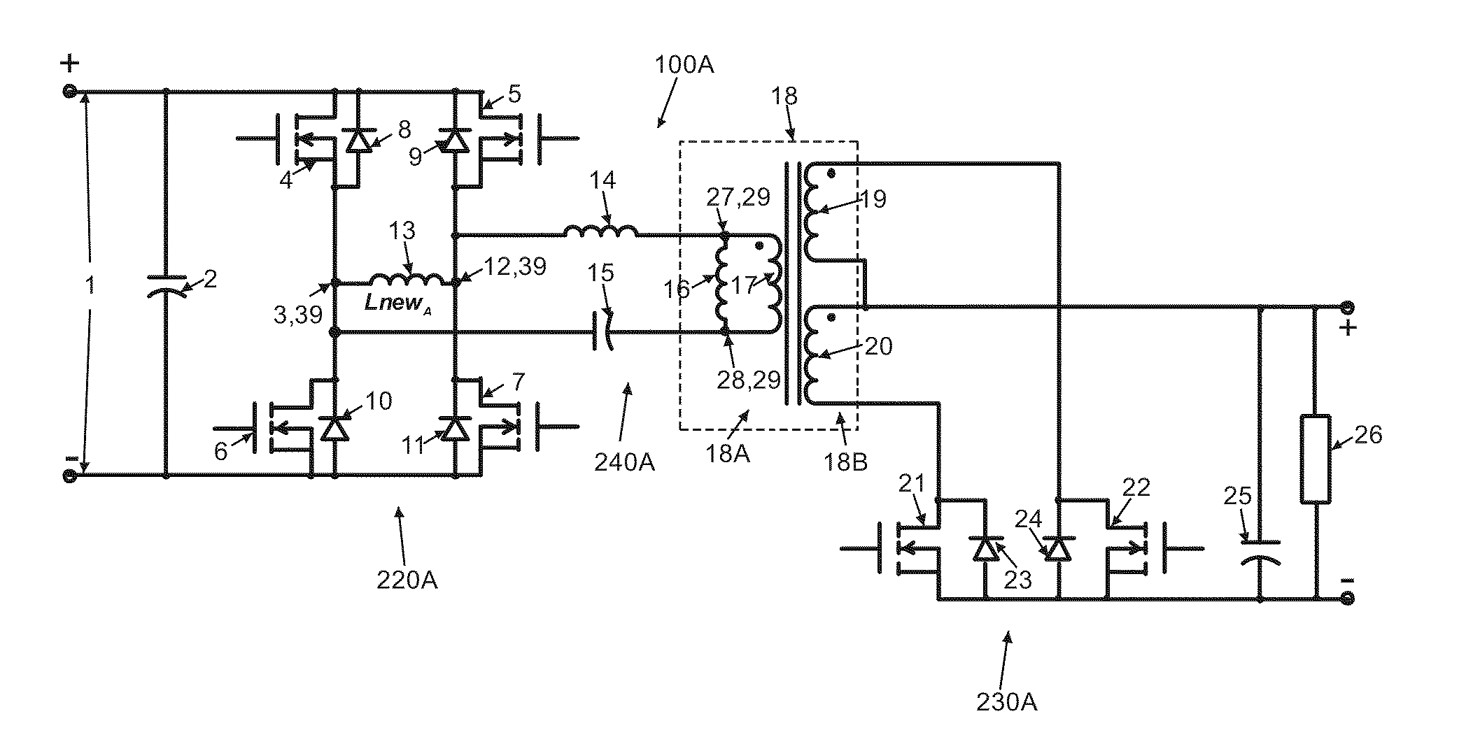
[0010]Various embodiments of the present invention can employ input, or primary section devices, that are connected in full-bridge, half-bridge, or push-pull switcher (“chopper”) configurations that chop the power source voltage (i.e. with the switching frequency), which is then applied to the resonant network circuit of the present invention, while the output, or secondary section devices, are connected in a full-bridge, half-bridge, or push-pull configurations and are controlled in a synchronous rectification manner. To reverse the direction of power transfer the control functions of the primary section devices and the secondary section devices are swapped (i.e. the devices that have performed synchronous rectification perform the “chopping” function while the former chopper devices perform the synchronous rectification function). The resonant circuit of various embodiments of the present invention is arranged in such a way that when its input / output terminals are swapped, which is the default function of the bi-directional converter, both loss-less switching (i.e. ZVS and ZCS operation) and the output voltage controllability of the circuitry is maintained.
[0011]In a first aspect of the invention, there is provided a bi-directional DC to DC converter that includes a first resonant tank circuit employed during power transfer along a first direction through the bi-directional DC to DC converter and a second resonant tank circuit employed during power transfer along a second direction through the bi-directional DC to DC converter. The second direction opposes the first direction.
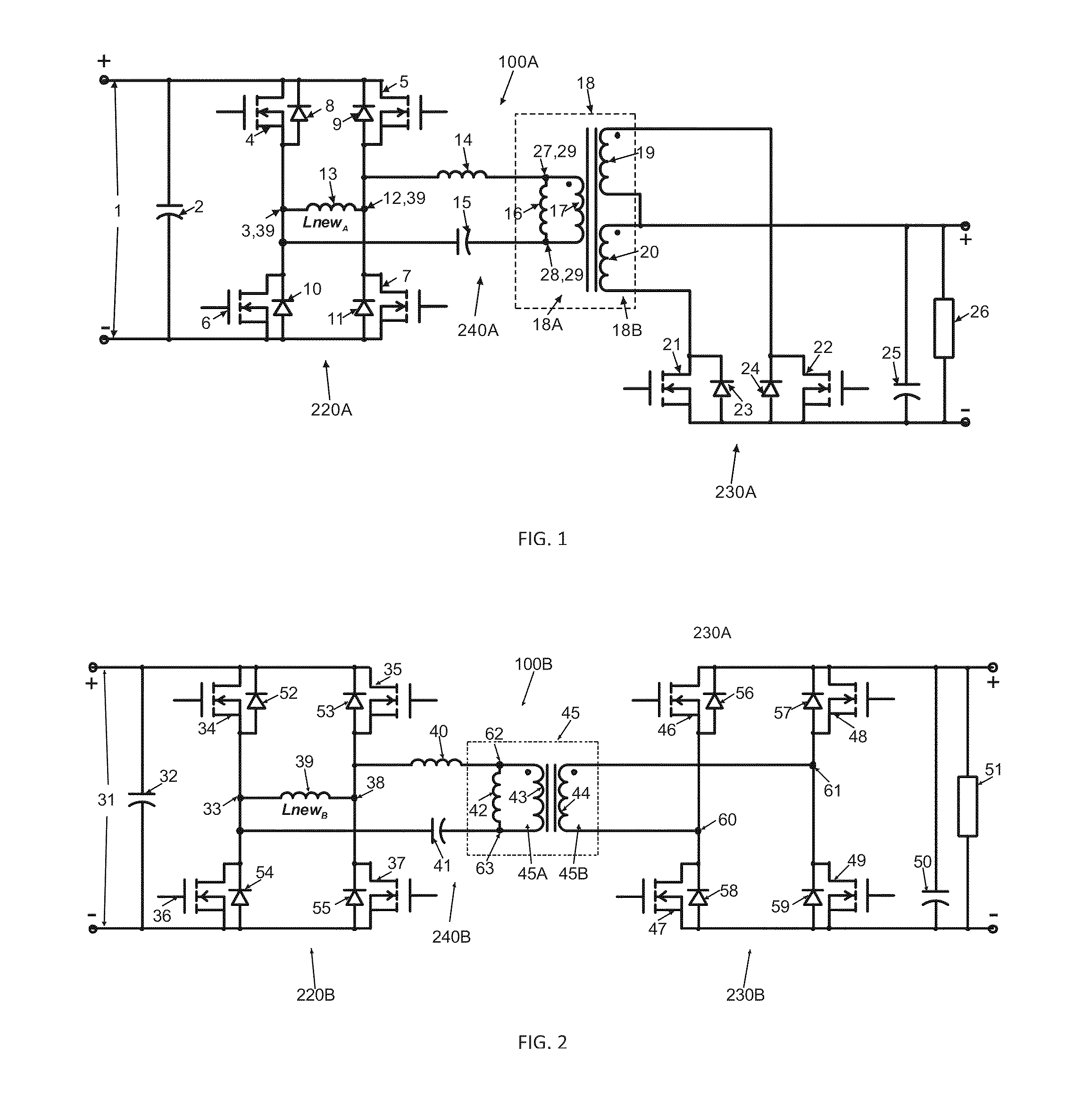
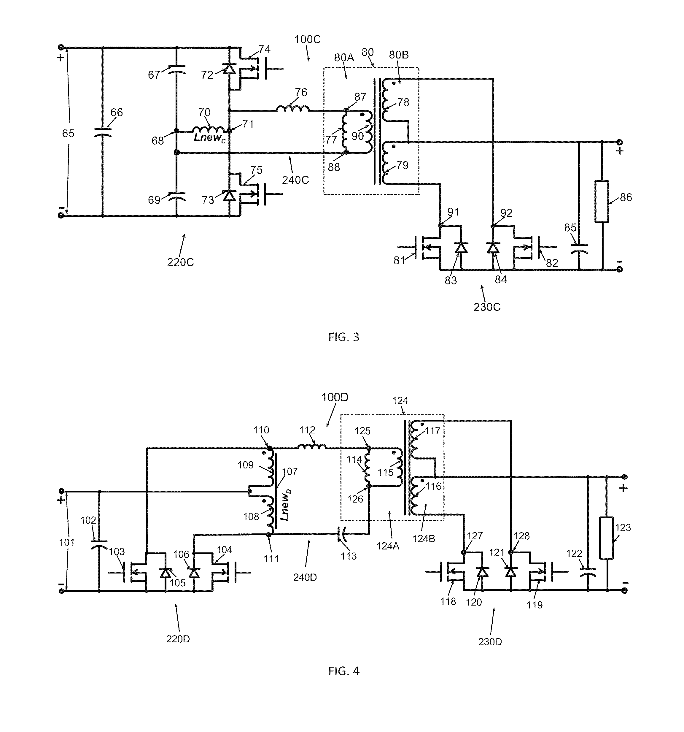
[0012]In a feature of this aspect of the invention, the first resonant tank circuit shares at least two common resonant components with the second resonant tank circuit and the first resonant tank circuit further includes a first resonant component that is different from a second resonant component of the second resonant tank circuit.
[0013]In another feature of this aspect, the at least two common resonant components include a capacitor connected in series with an inductor. The first resonant component includes a first inductor connected in series with the at least two common resonant components and the second resonant component includes a second inductor connected in series with the at least two common resonant components.
[0014]In yet another feature of this aspect, the at least two common resonant components are connected in series with a first load circuit and the first inductor is connected in parallel with the first load circuit during the power transfer along the first direction. The at least two common resonant components are connected in series with a second load circuit and the second inductor is connected in parallel with the second load circuit during the power transfer along the second direction.
[0015]In another feature of this aspect, the bi-directional DC to DC converter includes a transformer, the transformer including a primary side connected in series with the at least two common resonant components and connected in parallel with the first inductor. The at least two common resonant components are connected in series with a full-bridge switcher circuit and the second inductor is connected in parallel with the full-bridge switcher circuit. The transformer includes a secondary side connected to one of a full-bridge synchronous rectifier circuit, a half-bridge synchronous rectifier circuit and a push-pull synchronous rectifier circuit.

Problems solved by technology

The pulse width modulation techniques control techniques employed in these converters typically feature so called “hard-switching” which can lead to significant switching losses and adversely impact the ability to achieve high power densities and high power conversion efficiencies.

Method used


Image

  • Bi-directional power converter with regulated output and soft switching
  • Bi-directional power converter with regulated output and soft switching
  • Bi-directional power converter with regulated output and soft switching

Examples


Embodiment Construction

[0044]In the following description, certain specific details are set forth in order to provide a thorough understanding of various embodiments of the invention. However, one skilled in the art will understand that the invention may be practiced without these details. In other instances, well-known structures have not been shown or described in detail to avoid unnecessarily obscuring descriptions of the embodiments of the invention.

[0045]A schematic of an example embodiment of the bi-directional converter 100A embodying the principles of the present invention is shown in FIG. 1. In the case of power transfer from the left hand side to the right hand side of the circuitry in FIG. 1, a full-bridge switcher circuit 220A containing controlled switching devices 4, 5, 6, and 7 that include embedded, or external, anti-parallel diodes 8, 9, 10, and 11 is connected to a DC voltage source 1. Switching devices such as switching devices 4, 5, 6, and 7 employed by the present invention can includ...


PUM


Abstract

A resonant, bi-directional, DC to DC voltage converter with loss-less (soft) switching having regulated output and capable of converting power between two, high-potential and low-potential DC voltage sources. The converter's semiconductor and magnetic components provide both, output regulation and soft switching in both (step-down and step-up) directions of power conversion which reduces total component count, cost and volume and enhances power conversion efficiency.

Description

FIELD OF THE INVENTION[0001]The present invention relates to a bi-directional and isolated DC to[0002]DC power converters featuring soft, loss-less switching operation and output voltage controllability in both directions of power transfer. In addition, the present invention maintains the soft-switching operation and output voltage controllability within the entire load operating range (i.e. from no-load to full-load).BACKGROUND OF THE INVENTION[0003]Today's DC to DC switch mode power converters are typically required to provide insulation between the primary and secondary sides and to have high power density, high efficiency and low cost. In addition, many of applications including uninterruptable power supplies (UPS), power supplies utilizing renewable energy sources (e.g. solar, wind, fuel cells), as well as aerospace power supplies require bi-directional (step-up and step-down) power conversion with isolated and regulated output. Examples of isolated and pulse width modulation (...

Claims


Application Information

Patent Timeline
Patent Type & Authority Applications(United States)
IPC IPC(8): H02M3/335
CPCH02M3/33584H02M3/33592Y02B70/1475Y02B70/1433H02M3/3376Y02B70/10
Inventor ANGUELOV, GUEORGUI IORDANOVPETKOV, ROUMEN DIMITROV
Owner GREECON TECH
Why Eureka
Try Eureka