Electrosurgical pencil switch,circuitry, and method of assembly

a pencil switch and electrical technology, applied in the field of electrical surgical pencil switch, circuitry, and assembly method, can solve the problems of increasing costs, slow work by humans, and inability to group switches or switch components, and achieve the effects of low cost, easy assembly, and high quality

Active Publication Date: 2011-12-29
E SURGICAL
View PDF17 Cites 45 Cited by
  • Summary
  • Abstract
  • Description
  • Claims
  • Application Information

AI Technical Summary

Benefits of technology

[0075]Another object and advantage of this invention is production of switches and electrosurgical pencils having a limited number of parts, which are easily assembled.
[0076]Another object and advantage of this invention is production of switches and electrosurgical pencils having high quality electrical conductors, which may be reused many times with low cost replacement Pencils, at significant cost savings and reduced medical waste.
[0077]Another object and advantage of this invention is production of inexpensive switches and electrosurgical pencils which may be discarded as surgical waste after only a single use, thereby eliminating the cost of further handling, such as sterilization, and reducing biological hazard.
[0078]Another object and advantage of this invention is production of switches and electrosurgical pencils in which high quality, reusable, electrical conductors, may be positively joined to low cost replacement Pencils, to create a stable Pencil configuration when in use.
[0079]Another object and advantage of this invention is production of an electrosurgical pencils which unambiguously indicates to a user when the inexpensive disposable pencil and switch is properly connected to the more expensive, reusable, high quality electrical conductors.
[0080]Another object and advantage of this invention is production of multiple electrosurgical pencils in a continuous process, beginning with reels of sheet metal for the electrical components, through the automated over molding of non-conductive holding and insulating components, and automated assembly of such pencils to their final usable form.

Problems solved by technology

The largest single problem with most common switching arrangements is that, while the electrosurgical pencil switch circuitry of a single switch may be stamped in a single piece, the conducting strips of the circuitry must be stamped again at the “punch points” to electrically isolate each of the conducting strips.
As the electrical components of electrosurgical pencil switches are small, such work by humans is slow, sometimes inaccurate, and often requires special tools or fasteners.
Moreover, because switches are currently manufactured on assembly lines, such lines are formed to accommodate a stream of single switches, rather than allowing assembly of components when electrical conductors are “ganged,” or otherwise joined.
Where electrical conductor stamping for multiple switches does take place, the form of the electrical conductors, and the form of the non-electrical components, does not allow the assembly of switches as a group, or even as an attached line of switches or switch components.
As a result, the handling by human eyes, thought, and hands, and the consequent slowness and inaccuracies is magnified, thereby increasing costs.
Another large problem with all present electrosurgical pencils is that the entire assembly, from the active electrode all the way back to the electrical generator leads, and including the hand piece, with its switch and housing members, and also the electrical conductors by which the pencil is electrically connected to the generator, is discarded as medical waste.
However, like most manufactured items, and all medical tools (especially inexpensive medical tools), the cost of manufacture, and the distribution of electrosurgical pencils, along with the necessity to repurchase such “disposable” tools as they are discarded, adds greatly to their overall cost to the surgical profession and, ultimately, to their patients and health care costs.
No patent or electrosurgical pencil of which the inventor is aware allows automation of the assembly of the electrosurgical pencil hand piece, to reduce costs, and free up direct human attention and effort.
And no electrosurgical pencil of which the inventor is aware allows production and distribution cost savings, and “recycling” of the most expensive part of the pencil, the electrical generator conductors, so that these components may be used many times again.

Method used


Image

  • Electrosurgical pencil switch,circuitry, and method of assembly
  • Electrosurgical pencil switch,circuitry, and method of assembly
  • Electrosurgical pencil switch,circuitry, and method of assembly

Examples


first preferred embodiment

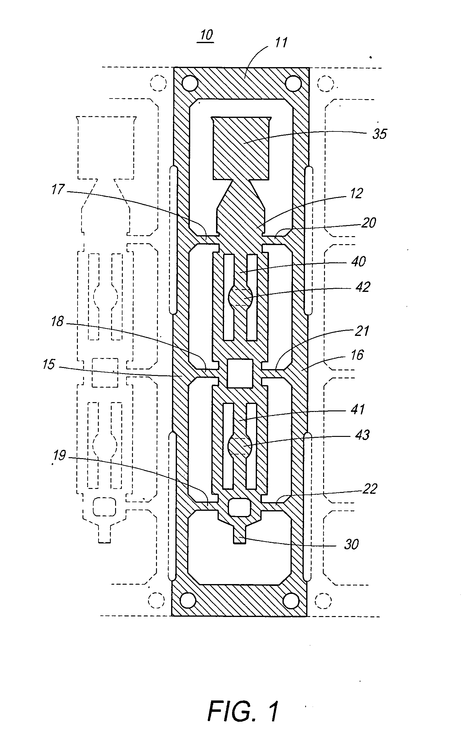
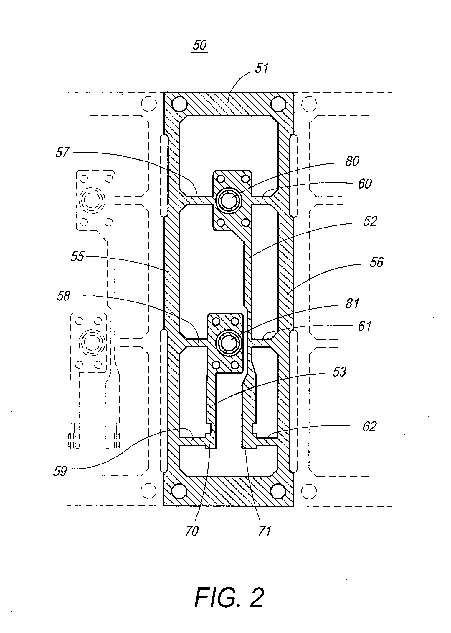
[0108]Referring initially to FIG. 1, a first embodiment of an electrical circuit First Frame of the Switch of the present invention is shown in top down, plan view. In FIG. 1, First Frame 10 of the present invention is comprised of a unitary piece, formed from a blank sheet of conductive metal by stamping. The single sheet may be in the form of a reel of electrically conductive material. Portion 11 of frame 10, presented in cross-hatched rendering, is intended to be encased in an insulated Cabinet body (not shown). The metal sheet from which frame 10 is stamped is thick enough and conductive enough to carry current sufficient to cut, coagulate, ablate, excise, cauterize, or seal tissues by application of electric current to biological tissue through an active electrode (not shown). Frame 10, once stamped, forms a first conducting strip 12, which provides an electrical connection between two or more additional conducting strips stamped from a Second Frame (shown in FIG. 2), to thereb...

second preferred embodiment

[0137]Turning now to FIG. 16, a second embodiment of an electrical circuit First Frame and molded Cabinet Top 590 of the Switch of the present invention is shown. In this second embodiment a First Frame 590 is, like the First Frame 10 of the first embodiment (FIG. 1), comprised of a unitary piece, formed from a blank sheet of conductive metal by stamping. Again, First Frame 590 may be formed from a single sheet, or a reel of electrically conductive material as shown in FIG. 1, and explained in the text which accompanies FIG. 1. FIG. 16 shows the molded Cabinet Top 590 of the Switch of the present invention in bottom up, plan view. Specifically, molded Cabinet Top 590 is shown prior to cutting through Frame Isthmus 517, 518, 519, 520, 521, and 522 to separate (and discard) exterior portions 515 and 516 from First frame 510. The Cabinet top molded base 591 (non-conductive exterior) is formed as a single piece, with conductive elements (the metal frame 510 of FIG. 16) embedded within. ...


PUM

PropertyMeasurementUnit
lengthaaaaaaaaaa
electrically conductiveaaaaaaaaaa
lengthaaaaaaaaaa

Abstract

Formation of an assemblage of electrically conductive components for a new electrosurgical pencil is disclosed, and assembly of those components in a method for automating the manufacture and combination of current carrying metal circuitry and operable switching components in “electrosurgical pencils” which supply current to an active terminal, for application of high frequency or high power electrical current to a surgical site, and control of such current through coaction of the elements of the switch. In manufacture, the design of the switch components allows start-to-finish automated assembly of the switch, whereby an array of identical multiple metal “frames” may be formed from a reel, then each frame separated and enclosed within molded plastic, and the resulting cabinet joined with a housing to create an inexpensive hand piece, for use with a high quality, reusable cable and plug assembly.

Description

CROSS REFERENCE TO RELATED APPLICATIONS[0001]This application is a continuation-in-part of application Ser. No. 12-456,622, from which applicant claims priority.TECHNICAL FIELD OF THE INVENTION[0002]The present invention relates to an assemblage of electrically conductive components for power switching in electrical apparatus hand pieces, and to automated assembly of the such components into a molded insulative holding and positioning body (herein the “Cabinet”). More specifically, the present invention is a method for automating the manufacture and combination of current carrying metal circuitry, and associated switching components, which allows further automated assembly of such circuitry, switching components, and a Cabinet into the hollow body housing of an electrosurgical apparatus. The assembly of the present invention creates an improved tool for surgical cutting, coagulation, and cauterizing. Such tools are generally referred to in surgery as “electrosurgical pencils” (“EP”)...

Claims


Application Information

Patent Timeline
Patent Type & Authority Applications(United States)
IPC IPC(8): H01H1/06H01H11/00A61B18/14
CPCA61B18/1402A61B2017/00526A61B2018/00178A61B2018/00922H01H9/0214Y10T29/49105H01H11/0056H01H2300/014Y10T29/49169Y10T29/49151Y10T29/49158H01H9/04
Inventor BLOMEYER, MICHAEL
Owner E SURGICAL
Why Eureka
Try Eureka