Aircraft actuator hydraulic system
a technology of hydraulic system and actuator, which is applied in the direction of power amplification, transportation and packaging, and parallel arrangement of servomotors, etc. it can solve the problems of significant constraint on continuous running time and oil replacement time associated with oil degradation, and increase the overall temperature of the hydraulic system, so as to suppress the increase in the temperature of the backup hydraulic pump
- Summary
- Abstract
- Description
- Claims
- Application Information
AI Technical Summary
Benefits of technology
Problems solved by technology
Method used
Image
Examples
first embodiment
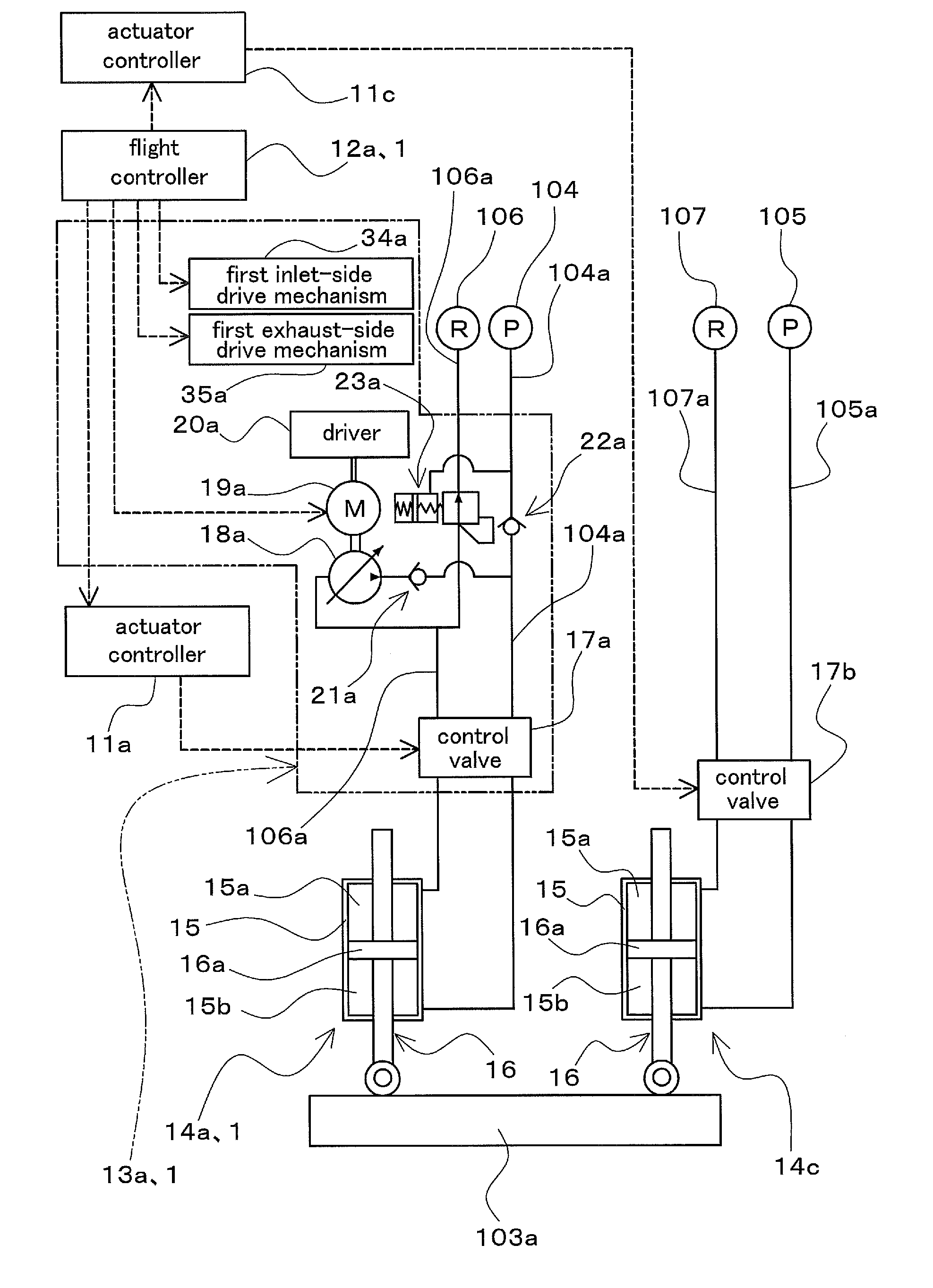
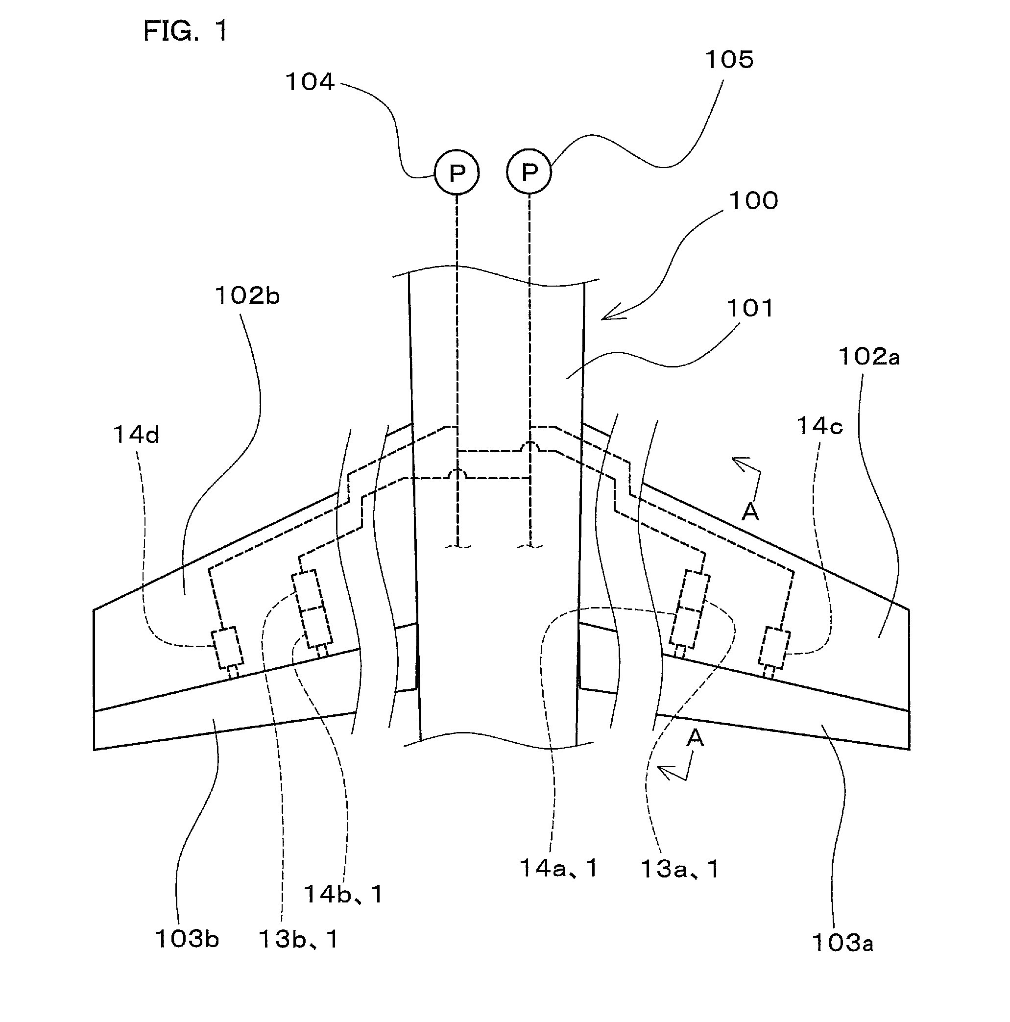
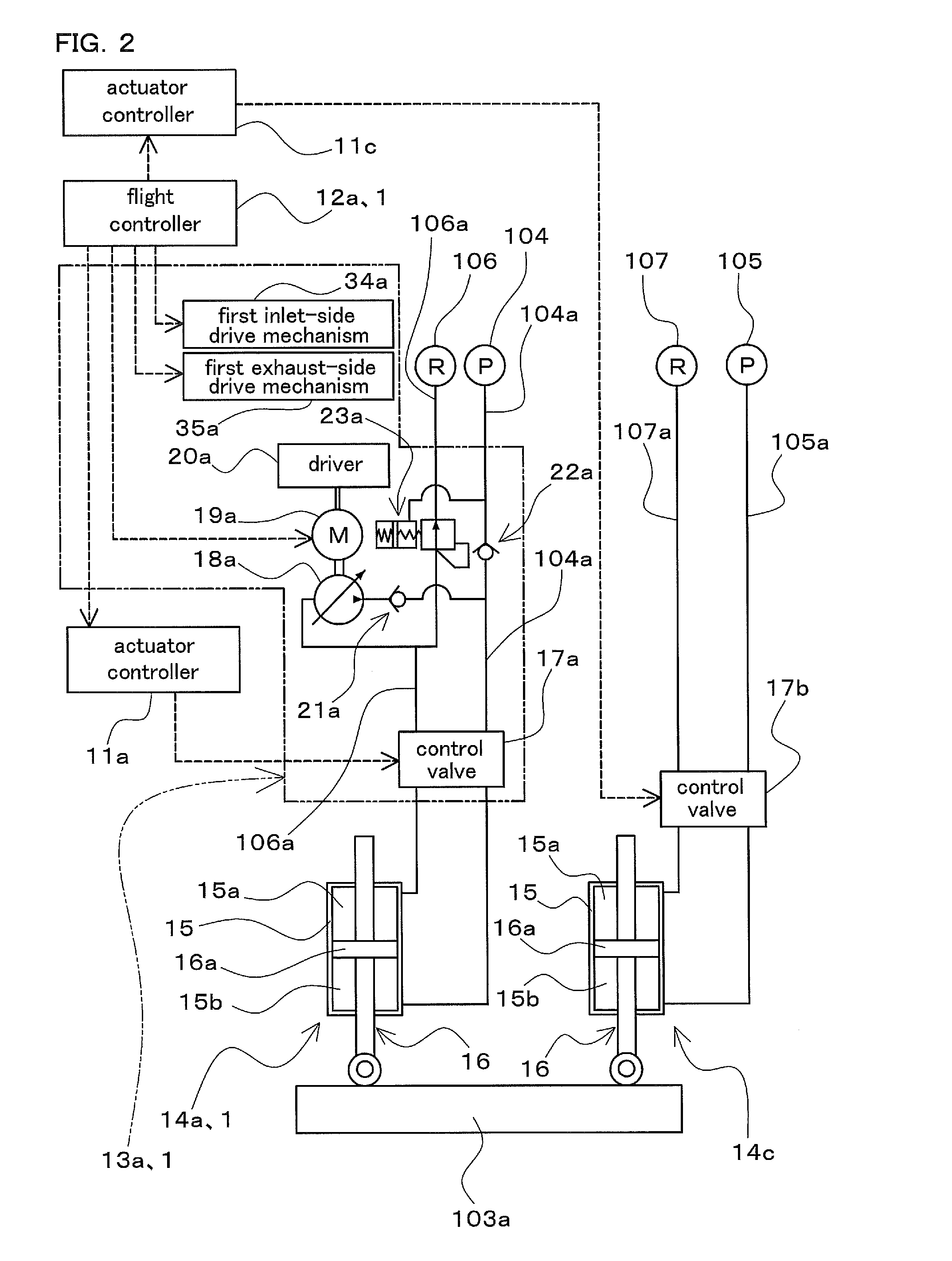
[0029]FIG. 1 is a diagram schematically showing part of an aircraft 100 to which a hydraulic system 1 for aircraft actuators (hereinafter, also simply referred to as a “hydraulic system 1”) according to a first embodiment of the present invention is applied, showing part of a fuselage portion of a body 101 of the aircraft 100 and a pair of main wings (102a, 102b). In FIG. 1, the illustration of the intermediate portions of the main wings (102a, 102b) is omitted.
[0030]The main wing 102a is provided with an aileron 103a as a moving surface (flight control surface) constituting a control surface of the aircraft 100. Likewise, the main wing 102b is provided with an aileron 103b as a moving surface (flight control surface) constituting a control surface of the aircraft 100. As illustrated in FIG. 1, the aileron 103a of the main wing 102a is configured to be driven by a plurality of (for example, two) actuators (14a, 14c). The aileron 103b of the main wing 102b is also configured to be dr...
second embodiment
[0107]Next, a hydraulic system 2 (hereinafter, also simply referred to as a “hydraulic system 2”) for aircraft actuators and a hydraulic system 3 for aircraft actuators (hereinafter, also simply referred to as a “hydraulic system 3”) according to a second embodiment of the present invention will be described. FIGS. 7 and 8 are schematic diagrams showing part of an aircraft 100 to which the hydraulic system 2 and the hydraulic system 3 are applied, showing a rear part of a body 101 of the aircraft 100, a pair of tailplanes (109a, 109b), and a vertical tail 111. Note that the vertical tail 111 is schematically shown as being separated from the body 101.
[0108]The hydraulic system 2 shown in FIG. 7 includes a first actuator 14a and a second actuator 14b, hydraulic apparatuses (13a, 13b), and flight controllers (12a, 12b) (not shown), as with the hydraulic system 1 of the first embodiment. However, the configuration of the hydraulic system 2 is different from that of the hydraulic system...
PUM
 Abstract
Description
Claims
Application Information
 - R&D
- Intellectual Property
- Life Sciences
- Materials
- Tech Scout
- Unparalleled Data Quality
- Higher Quality Content
- 60% Fewer Hallucinations
Browse by: Latest US Patents, China's latest patents, Technical Efficacy Thesaurus, Application Domain, Technology Topic, Popular Technical Reports.
© 2025 PatSnap. All rights reserved.Legal|Privacy policy|Modern Slavery Act Transparency Statement|Sitemap|About US| Contact US: help@patsnap.com


