
Carbon dioxide capture and liquefaction

a carbon dioxide and liquefaction technology, applied in the field of carbon dioxide capture and liquefaction, can solve the problems of little incentive to develop the technology necessary to carry out this sequestration step, low economic advantage, and soon economic disruption to the status quo, so as to minimize energy consumption and increase economic advantage

Active Publication Date: 2012-01-12
KELLER ARNOLD
View PDF10 Cites 54 Cited by
  • Summary
  • Abstract
  • Description
  • Claims
  • Application Information

AI Technical Summary

Benefits of technology

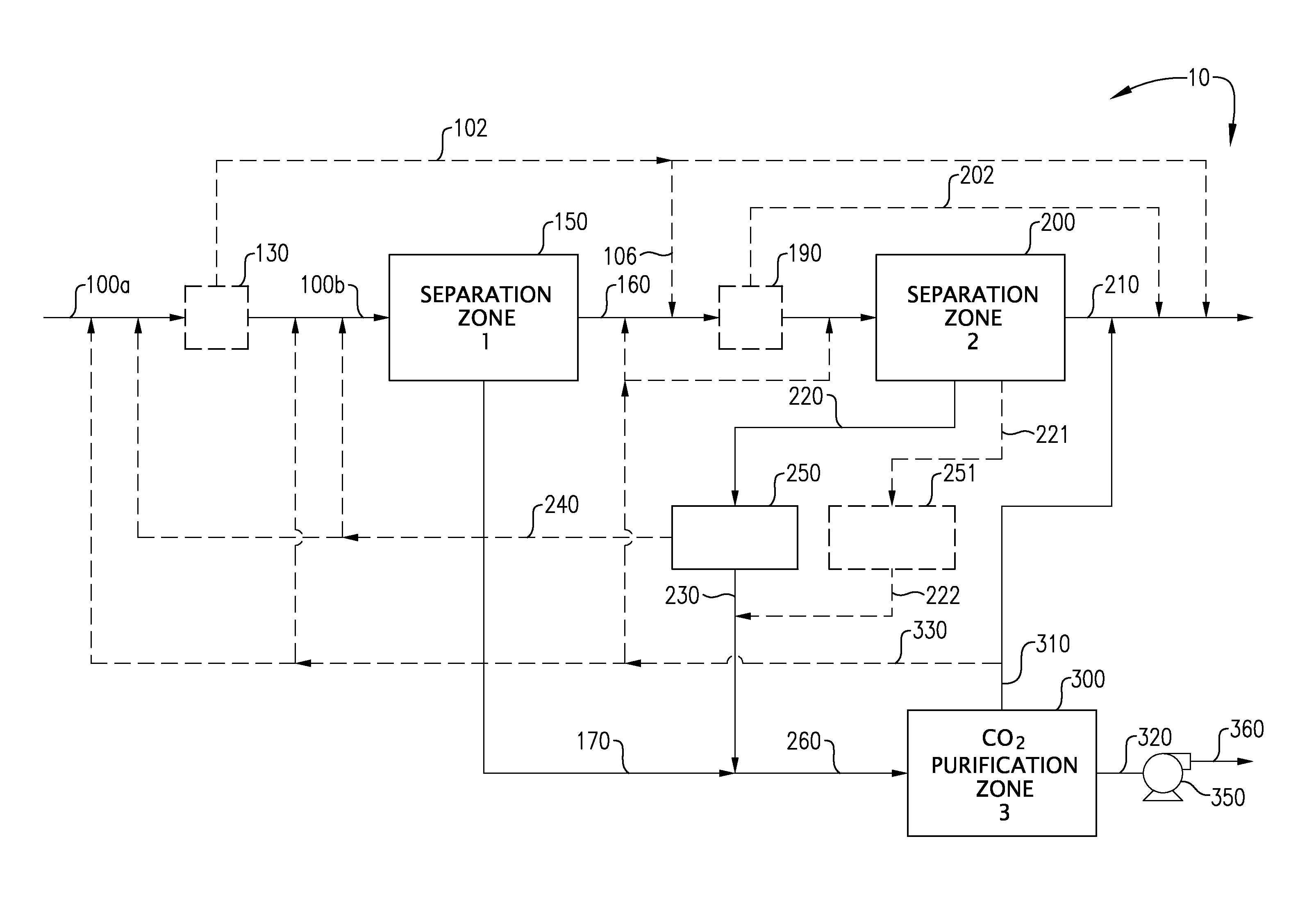
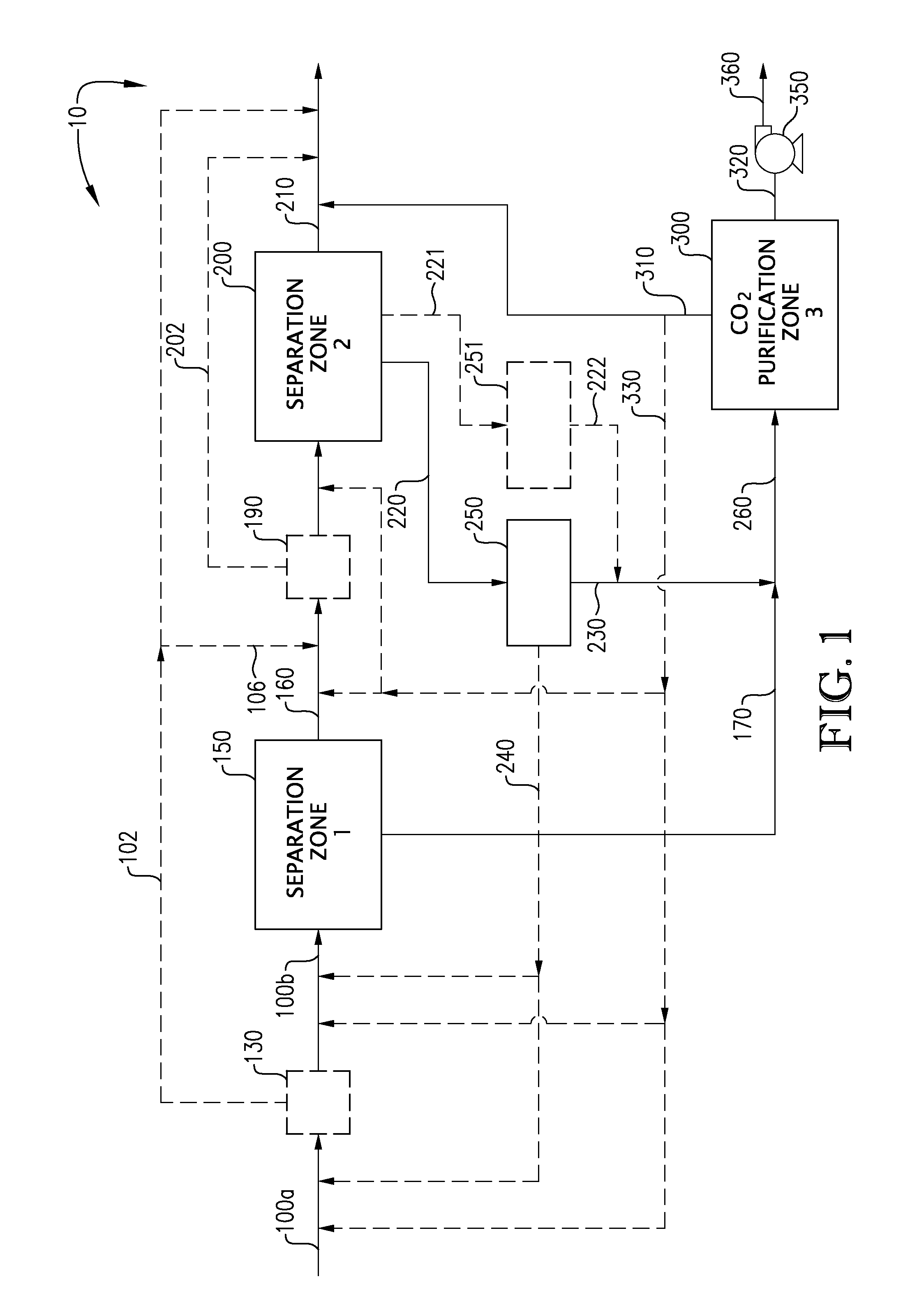
[0014]Carbon dioxide recovery processes and systems configured according to one or more embodiments of the present invention can comprise a first separation zone, for removing CO2 from a substantially dry and nearly sulfur compound-free high pressure feed gas stream and a second separation zone for further separating CO2 from the remaining feed gas stream by adsorbing, absorbing, or solidifying by freezing at least a portion of the CO2 remaining in the feed gas stream. The processes and systems of the present invention can be more efficient, and thereby provide a bigger economic advantage, than conventional CO2 capture and removal systems and processes. Processes and systems as described herein can minimize energy consumption by maintaining the pressure of one or more of the feed gas stream, the recovered, purified CO2 liquid stream, and / or one or more interim process streams (e.g., the condensed CO2-rich fraction withdrawn from the first separation zone and the CO2-rich liquid stream exiting the second separation zone) at a pressure greater than 77, 100, 500, or 650 psia. In another embodiment, the pressure of one or more of these streams can be at a pressure greater than the triple point pressure of CO2 (e.g., 77 psia), and / or at a pressure in the range of 77 to 1070 psia, 640 to 1016 psia, or 700 to 910 psia.

Problems solved by technology

The product of combustion in the manufacture of power and in other combustion processes results in the emission of CO2 to the atmosphere.
Until now, there has been no economic incentive to capture and sequester CO2, and, therefore, there has been little incentive to develop the technology necessary to carry out this sequestration step.
With the impending legislation in the US and abroad, there will soon be an economic disruption to the status quo of simply discharging CO2 to the atmosphere.
The studies demonstrated that the consequence of CO2 sequestration have added a considerable economic penalty with regard to energy production costs in the form of additional capital expenditures and increased operating costs.
Unfortunately, this stream typically also contains H2S and COS, both of which are undesirable constituents.
There are differences in the current physical solvent processes that result in differences in both the capital and operating cost.
However, each of these processes suffers from a common drawback: each process regenerates its solvent by releasing the entire amount of captured CO2 at relatively low pressures.
This common problem results in the energy requirement to compress the entire captured CO2 from approximately atmospheric pressure to a super critical pressure needed for sequestration.
As a result, the overall cost of equipment and energy required for the CO2 compression (and subsequent purification) is a major cost burden on the current CO2 capture-compression processes.

Method used


Image

  • Carbon dioxide capture and liquefaction
  • Carbon dioxide capture and liquefaction
  • Carbon dioxide capture and liquefaction

Examples


example 1

Simulation of a CO2 Recovery Facility Utilizing an Absorption Stage

[0111]The system depicted in FIGS. 4a and 4b was modeled using the PD-Plus Chemical Process Simulator (available from Deerhaven Technical Software, Moultonborough, N.H.). Table 5, below, presents the Heat & Material Balance (HMB) obtained from the simulation of the CO2 recovery facility that utilizes an absorption stage in the second separation zone.

TABLE 5Heat and Material Balance for CO2 Recovery Facility Utilizing Absorption Stage (FIGS. 4a and 4b)Stream Number123A34Temperature (° F.)45.72.6−2−2.1−19.5Pressure (psia)659.2651.2643.2643.2635.2Fraction Liquid00000.0536LBMOL / HRHYDROGEN68,164.3068,164.3068,164.3069,155.8068,164.30CARBON MONOXIDE1,031.101,031.101,031.101,064.001,031.10METHANE500.70500.70500.70528.70500.70CARBON DIOXIDE62,901.6062,901.6062,901.6064,259.1062,901.60NITROGEN4,683.904,683.904,683.904,865.604,683.90TOTAL137,281.60137,281.60137,281.60139,873.20137,281.60Stream Number56789Temperature (° F.)−38−...

example 2

Simulation of a CO2 Recovery Facility Utilizing an Adsorption Stage

[0112]The system depicted in FIGS. 5a and 5b was modeled using the PD-Plus Chemical Process Simulator (available from Deerhaven Technical Software, Moultonborough, N.H.). Table 6, below, presents the Heat & Material Balance (HMB) obtained from the simulation of the CO2 recovery facility that utilizes an adsorption stage in the second separation zone.

TABLE 6Heat and Material Balance for CO2 Recovery Facility Utilizing Adsorption Stage (FIGS. 5a and 5b)Stream Number12345Temperature (° F.)45.73.9−2−17.8−38Pressure (psia)659.2651.2643.2635.2627.2Liquid Fraction0000.03120.2184HYDROGEN68,164.3068,164.3068,164.3068,164.3068,164.30CARBON MONOXIDE1,031.101,031.101,031.101,031.101,031.10METHANE500.70500.70500.70500.70500.70CARBON DIOXIDE62,901.6062,901.6062,901.6062,901.6062,901.60NITROGEN4,683.904,683.904,683.904,683.904,683.90TOTAL137,281.60137,281.60137,281.60137,281.60137,281.60Stream Number678910Temperature (° F.)−38−38−4...

example 3

Simulation of a CO2 Recovery Facility Utilizing a Deliberate Freezing Stage

[0113]The system depicted in FIGS. 6a and 6b was modeled using the PD-Plus Chemical Process Simulator (available from Deerhaven Technical Software, Moultonborough, N.H.). Table 7, below, presents the Heat & Material Balance (HMB) obtained from the simulation of the CO2 recovery facility that utilizes a deliberate freezing stage in the second separation zone.

TABLE 7Heat and Material Balance for CO2 Recovery Facility Utilizing Freezing Stage (FIGS. 6a and 6b)Stream Number12345Temperature (° F.)45.70.1−2−18.6−38Pressure (psia)659.2651.2643.2635.2627.2Liquid Fraction0000.04240.2184HYDROGEN68,164.3068,164.3068,164.3068,164.3068,164.30CARBON MONOXIDE1,031.101,031.101,031.101,031.101,031.10METHANE500.70500.70500.70500.70500.70CARBON DIOXIDE62,901.6062,901.6062,901.6062,901.6062,901.60NITROGEN4,683.904,683.904,683.904,683.904,683.90TOTAL137,281.60137,281.60137,281.60137,281.60137,281.60Stream Number678910Temperature ...


PUM

PropertyMeasurementUnit
pressureaaaaaaaaaa
pressureaaaaaaaaaa
boiling pointaaaaaaaaaa

Abstract

An energy-efficient method of recovering carbon dioxide (CO2) in a high-pressure liquid state from a high-pressure gas stream. The method includes cooling, condensing, and / or separating CO2 from a high-pressure gas stream in two or more separation zones and further purifying the resulting sub-critical pressure liquid CO2 streams in a third purification zone to thereby provide purified CO2. The purified liquid CO2 may be pumped to above the critical pressure for further utilization and / or sequestration for industrial or environmental purposes.

Description

CROSS-REFERENCE TO RELATED APPLICATIONS[0001]This application claims benefit under 35 U.S.C. §119(e) based on U.S. Provisional Application No. 61 / 362,968, filed on Jul. 9, 2010, the entire disclosure of which is incorporated herein by reference.FIELD OF THE INVENTION[0002]This invention generally relates to methods of removing carbon dioxide from a high-pressure gas stream substantially free from water vapor and sulfur compounds and recovering the high-pressure substantially pure liquefied carbon dioxide for further use, processing, and / or storage.BACKGROUND[0003]There is current interest in capturing carbon dioxide (CO2) from industrial processes and sequestering (or storing) the captured CO2 in a way to prevent CO2 gas from entering the atmosphere. The product of combustion in the manufacture of power and in other combustion processes results in the emission of CO2 to the atmosphere. These CO2 emissions are believed by some scientists to contribute to global warming. As a result, ...

Claims


Application Information

Patent Timeline
Patent Type & Authority Applications(United States)
IPC IPC(8): F25J3/08F25J3/00C01B32/50
CPCC01B3/501F25J1/0027C01B3/52C01B2203/04C01B2203/0405C01B2203/0415C01B2203/0475C10L3/104F25J3/0209F25J3/0223F25J3/0252F25J3/0266F25J2200/02F25J2200/74F25J2205/04F25J2205/20F25J2205/24F25J2205/40F25J2205/60F25J2210/70F25J2215/04F25J2220/82F25J2220/84F25J2235/80F25J2245/02F25J2270/60F25J2270/90F25J2280/30F25J2290/34Y02C10/12F25J2205/50F25J2210/04C10K1/002C10K1/004C10K1/005C10K1/165C10K3/04C10G2300/1025C10G2300/44C01B3/506F25J2215/02F25J3/0233Y02P30/00Y02P20/10Y02C20/40Y02P20/151
Inventor KELLER, ARNOLD
Owner KELLER ARNOLD
Learn More