
Method and control device for determining a characteristic viscosity variable of an oil

a technology of oil viscosity and control device, which is applied in the direction of electrical control, non-mechanical valves, instruments, etc., can solve the problem of fluctuation in the effectiveness of hydraulic control means, and achieve the effect of preventing engine damage and high viscosity

Inactive Publication Date: 2012-01-12
SCHAEFFLER TECH AG & CO KG
View PDF4 Cites 12 Cited by
  • Summary
  • Abstract
  • Description
  • Claims
  • Application Information

AI Technical Summary

Benefits of technology

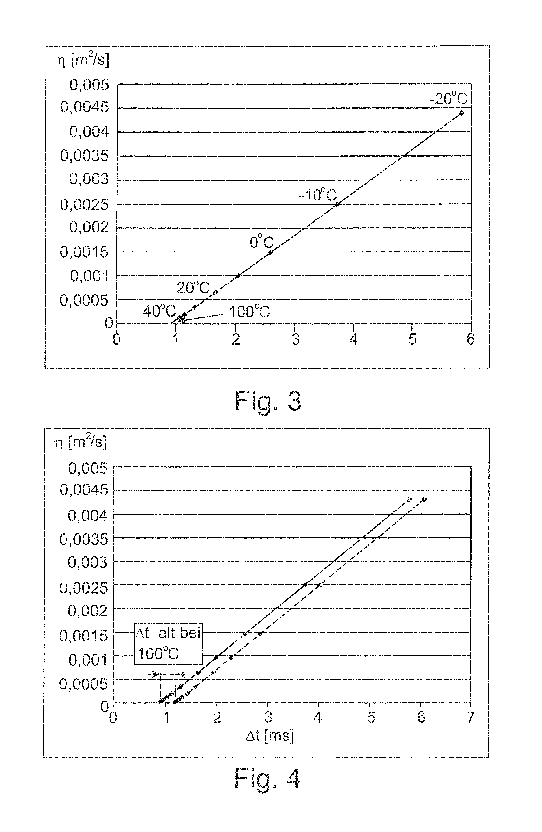
[0014]The particular advantage of evaluating the time period of the adjusting movement of the hydraulic component during the ballistic movement is that of—in contrast to computer determination from the oil temperature—the actual system behavior, which is induced by the viscosity, being evaluated and therefore a direct characteristic variable for the current viscosity being obtained. A more definite and reliable conclusion about the actual value of the viscosity can be drawn solely from detecting the time period. In comparison to only indirect determination by means of the temperature of the engine oil, the properties of the oil are directly detected by means of the movement sequence of the component in this method, and therefore aging effects of the engine oil can also be detected.
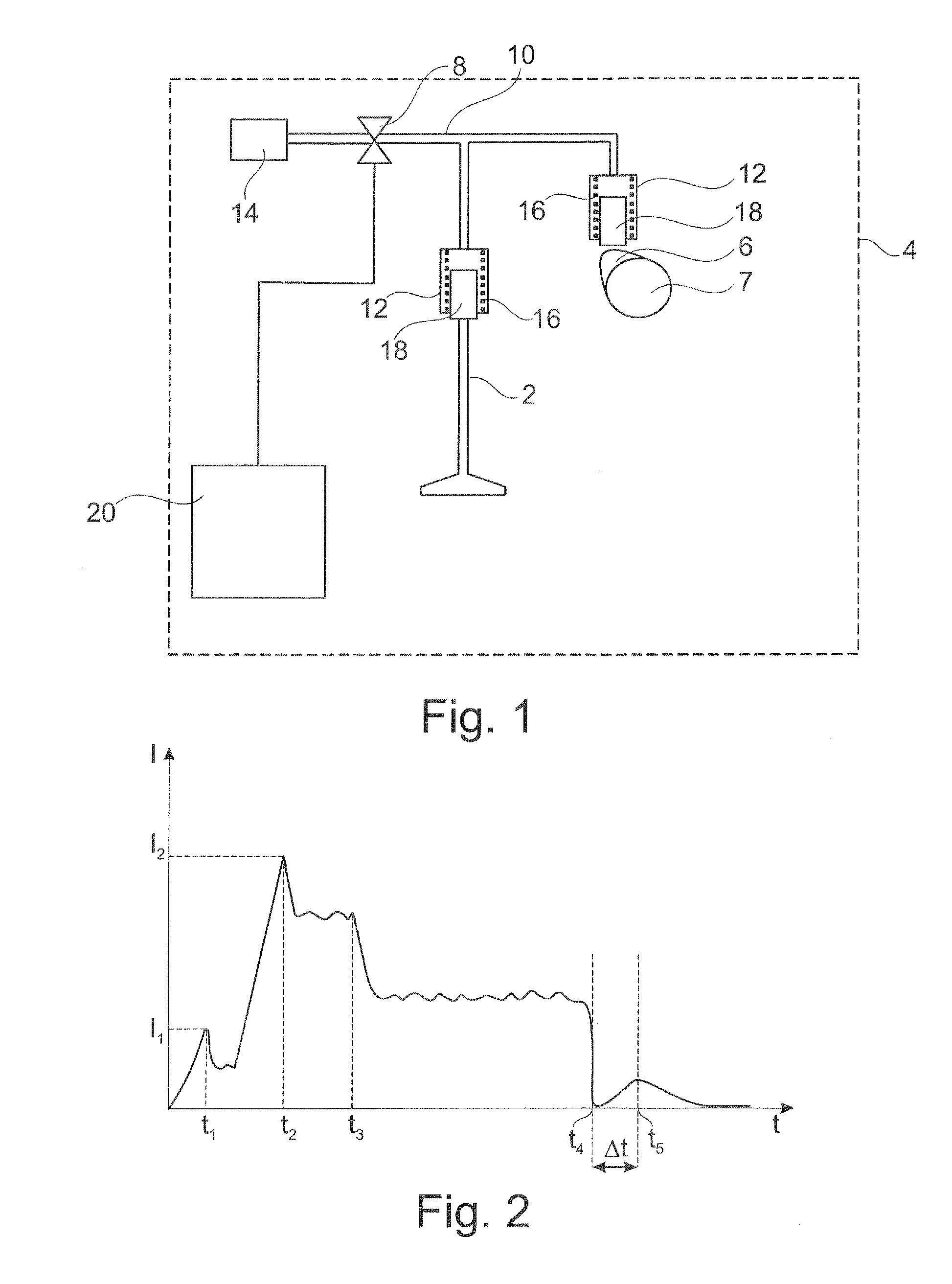
[0016]According to a preferred development, the time or adjustment period is determined from a control signal of the switching valve, in particular from the field current of said switching valve. Therefore, no additional measuring devices, such as position sensors, are required according to this preferred refinement. The time period and therefore the viscosity are therefore determined solely by evaluation (using software), without additional hardware components being required. As a result, the costs of a system of this kind are kept low.
[0025]However, provision is preferably made for aging of the hydraulic component to also be derived from the determined time period at a defined operating point. The defined operating point is, in particular, a high engine oil temperature, preferably a temperature of >80° C. and, in particular, >100° C. On account of a measure of the aging being derived from the time period, the actual behavior of the system and not, for example, only a postulated behavior of the system is evaluated—as is already the case when establishing the characteristic viscosity variable for the oil. Therefore, the direct evaluation understood in this sense is more accurate and more reliable. The preferred evaluation at a high engine oil temperature is based on the consideration that, at these high temperatures, the influence of the viscosity of the oil on the time period is at least negligible on account of the very low viscosity, which tends toward zero, at high temperatures. At these high temperatures, the time period is therefore established solely by the configuration of the switching valve.
[0033]According to a preferred refinement, provision is also made for a warning signal to be output when the determined oil viscosity does not permit disturbance-free operation of the engine. Furthermore, provision is made for even starting of the engine to be suppressed, in order, for example, to prevent damage to the engine on account of excessively high viscosity and the associated lack of lubrication of the engine. This is advantageous, for example, in winter when the initial viscosity during cold-starting is too high on account of the external temperatures. Therefore, a minimum external temperature which must not be undershot can be established on the basis of the oil state determined in a preceding operating cycle.

Problems solved by technology

In particular, the effectiveness of the hydraulic control means is sensitive to fluctuations in the viscosity of the oil used.
This temperature-dependent and therefore indirect determination operation has disadvantages and does not take into consideration, for example, aging of the engine oil or wear of the hydraulic components.

Method used


Image

  • Method and control device for determining a characteristic viscosity variable of an oil
  • Method and control device for determining a characteristic viscosity variable of an oil
  • Method and control device for determining a characteristic viscosity variable of an oil

Examples


Embodiment Construction

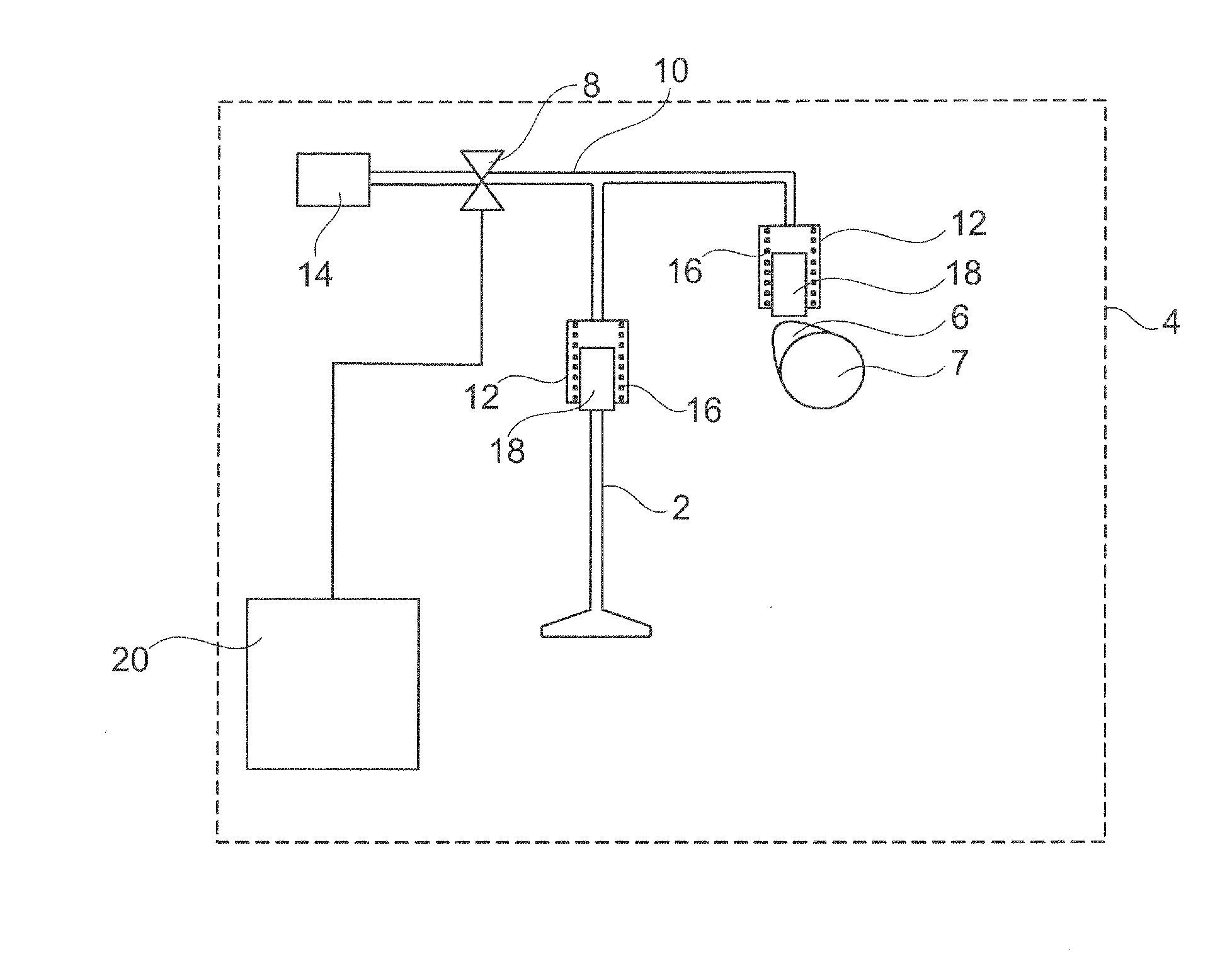
[0042]An electrohydraulic control system for hydraulically controlling a gas exchange valve 2 in a motor vehicle 4 which is indicated by a dashed border in FIG. 1 comprises a hydraulic system which transmits a movement of a cam 6 of a camshaft 7 to a respective gas exchange valve 2 by means of a hydraulic liquid, specifically the engine oil. The electrohydraulic valve control means is known per se. An essential feature is a switching valve which, in particular, is in the form of a solenoid valve 8 and is connected in a hydraulic line 10. The hydraulic line 10 is connected firstly to the cam 6 and secondly to the gas exchange valve 2 via a hydraulic cylinder 12. The hydraulic line 10 to a compensation or pressure chamber 14 can be blocked by means of the solenoid valve 8. Pistons 18 are mounted within the hydraulic cylinder 12, for example such that they can be moved against the force of a spring 16. In the event of rotation of the cam 6, the piston 18 of the associated hydraulic cyl...


PUM


Abstract

In order for the viscosity of the engine oil to be determined as directly as possible, particularly in the case of a motor vehicle with hydraulic control of the gas exchange valves, provision is made for a time period which a hydraulic component, in particular a solenoid valve, requires to move from a first position to a second position to be used as a measure of the viscosity. In particular, an electrical control signal for the solenoid valve is evaluated in the process. An additional sensor arrangement is not required. The determined viscosity is preferably actively used for controlling the gas exchange valves.

Description

CROSS-REFERENCE TO RELATED APPLICATION[0001]This application claims the benefit of DE 10 2010 020 754.3 filed May 17, 2010, which is incorporated by reference herein.FIELD OF THE INVENTION[0002]The invention relates to a method and to a control device for determining a characteristic viscosity variable of an oil in a machine with hydraulic control, in particular of an engine oil in a motor vehicle preferably with hydraulic control of the gas exchange valves, with a hydraulic component being adjusted from a first position to a second position with the aid of a control signal.BACKGROUND OF THE INVENTION[0003]In modern motor vehicles, the so-called gas exchange valves, that is to say the inlet and / or outlet valves for the motor vehicle engine, are nowadays controlled in a load-dependent manner for the purposes of minimizing pollutants and reducing consumption. Various systems are used in the process. All systems share the common feature that the closing and / or opening times of the gas ...

Claims


Application Information

Patent Timeline
IPC IPC(8): F01L9/02F01L9/14
CPCF01L9/025F01M1/18F02D41/0002F02D2041/001Y02T10/42F02D2041/2058F16N2250/36G01N11/00G01N33/2888F02D2041/2055Y02T10/40F01L9/14
Inventor PETZ, ANDREASTRAVERSA, PIERGIACOMODI PACE, MARCOTARASSOV, ILIA
Owner SCHAEFFLER TECH AG & CO KG
Learn More