Vehicular charge apparatus

a technology of electric charge and charge apparatus, which is applied in the direction of electrochemical generators, secondary cell servicing/maintenance, transportation and packaging, etc., can solve the problems of user troublesome operation or preparation operation before charge start, undetectable action, etc., and achieve the effect of reducing the troublesome charge operation of users

Inactive Publication Date: 2012-01-12
DENSO CORP
View PDF15 Cites 53 Cited by
  • Summary
  • Abstract
  • Description
  • Claims
  • Application Information

AI Technical Summary

Benefits of technology

[0017]The present invention takes the above problem into consideration. It is an object of the present invention to provide a vehicular charge apparatus to enable a prior detection of an action of a user, who intends to charge, beforehand and reduce a troublesomeness in the charge operation of the user.

Problems solved by technology

However, in such a conventional technology, the charge is triggered by inserting the charging paddle in the paddle slot.
Any action that is operated or prepared before the start of the charge is undetectable.
The preparation operation prior to charge may be troublesome for users.

Method used


Image

  • Vehicular charge apparatus
  • Vehicular charge apparatus
  • Vehicular charge apparatus

Examples


first embodiment

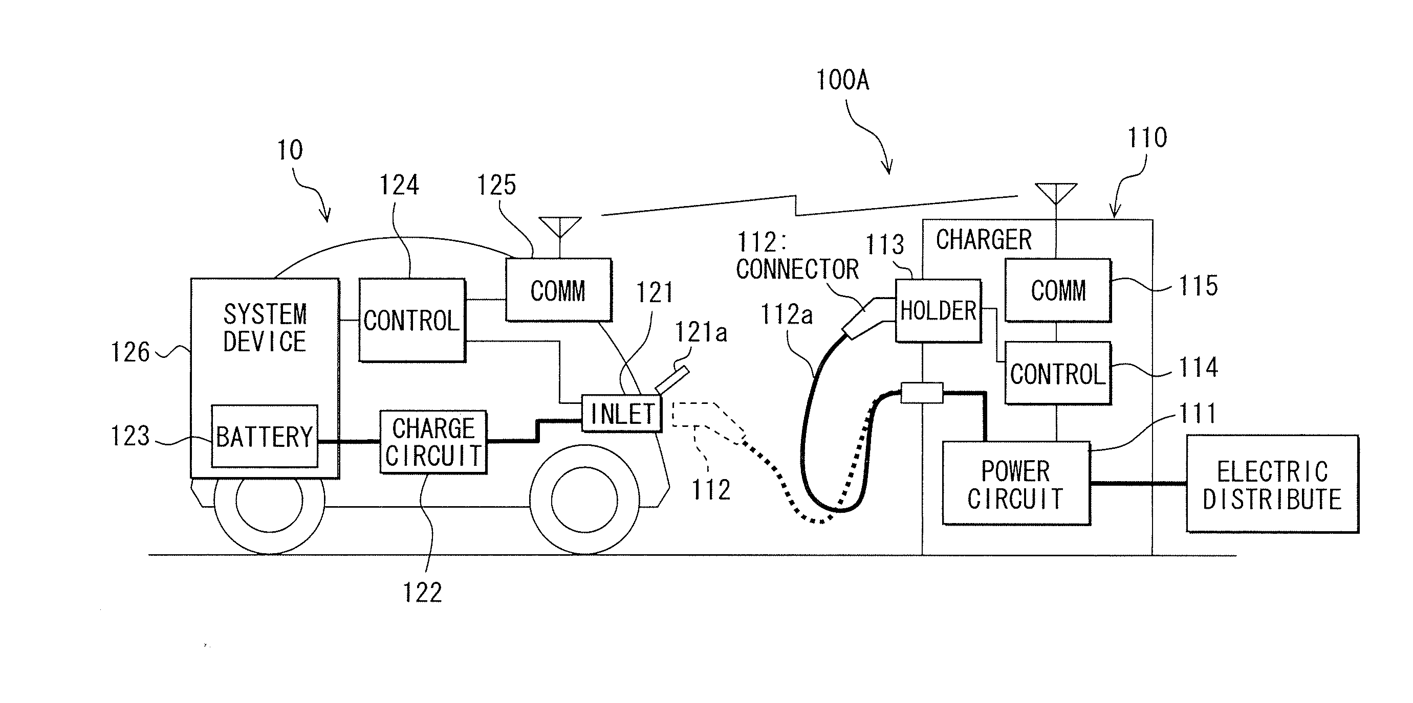
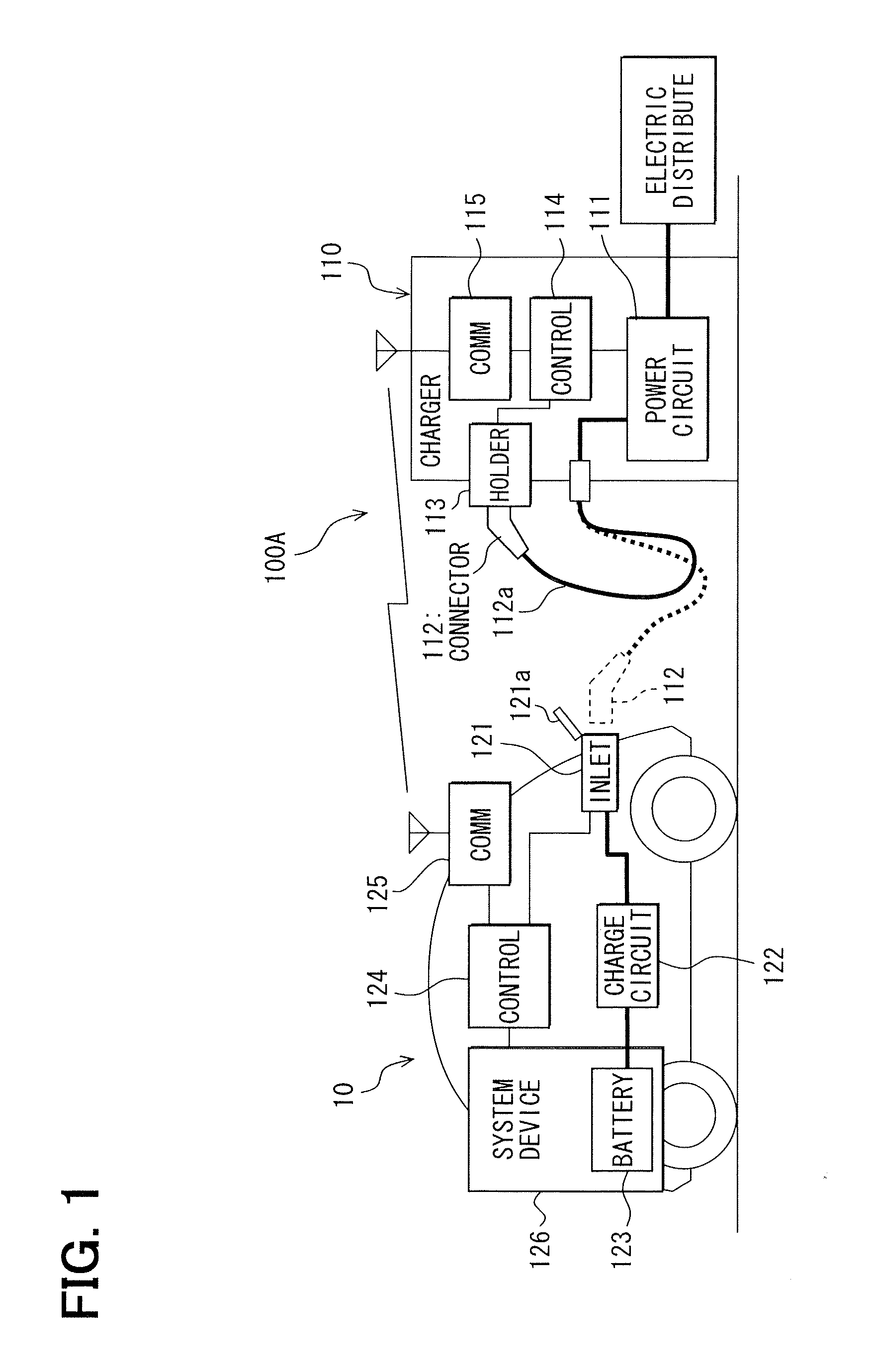
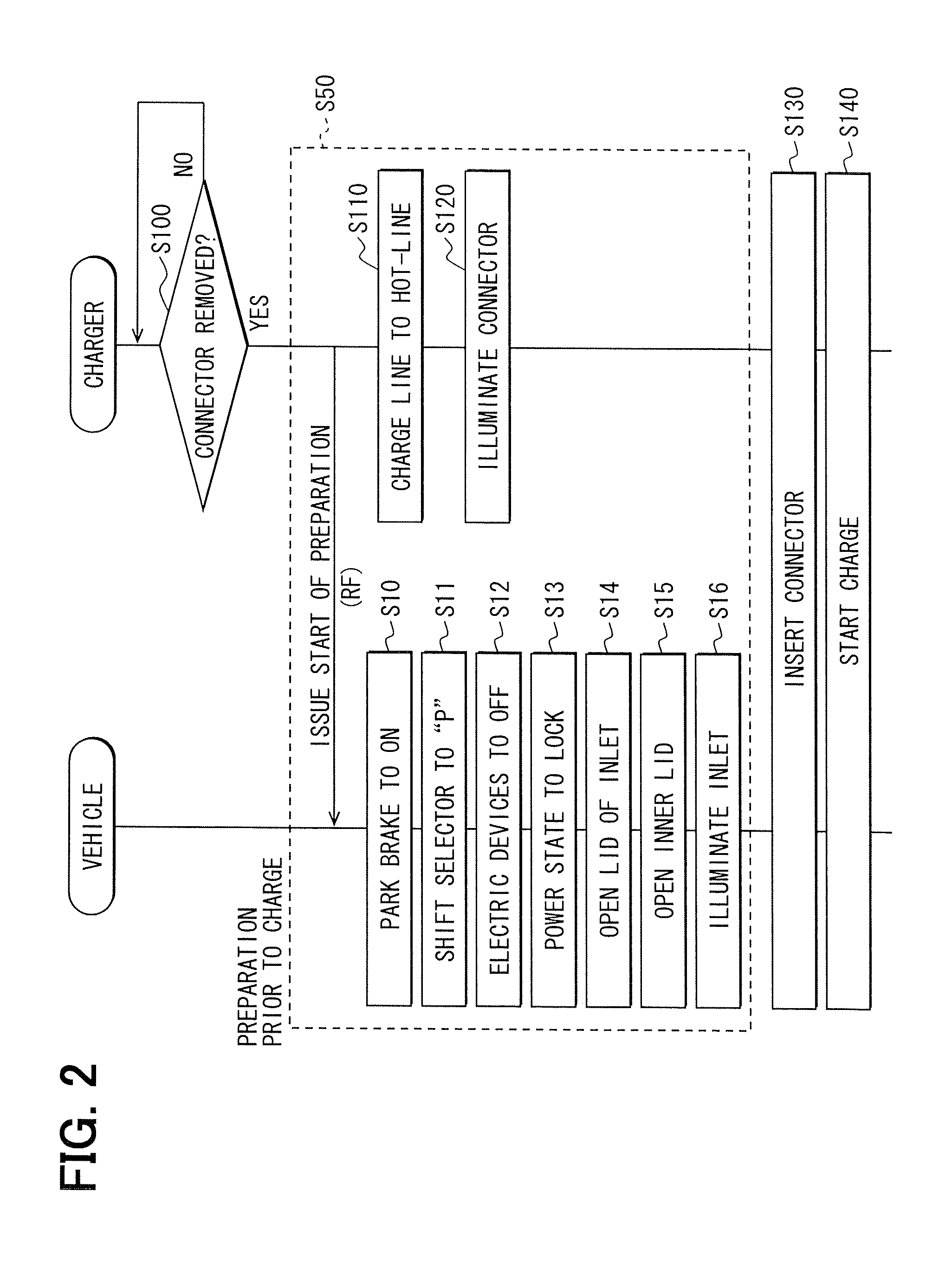
[0041]In a first embodiment of the present invention, a vehicular charge apparatus 100 for vehicles is directed to a vehicular charge apparatus 100 (100A) for externally charging an in-vehicle battery of a vehicle such as an electric vehicle (EV) or a plug-in hybrid vehicle (PHV). The following will explain a basic configuration of the vehicular charge apparatus 100A with reference to FIG. 1 and FIG. 2. FIG. 1 is a schematic view indicating the vehicular charge apparatus 100A. FIG. 2 is a flowchart diagram illustrating a charge process in the vehicular charge apparatus 100A.

[0042]The vehicular charge apparatus 100A is arranged in a charge station that serves as a charge facility and executes a quick charge. When needing a short time charge (e.g., thirty minute charge), a user drives a vehicle 10 to the charge station, charging the vehicle. The charge station is installed nationwide, for example, in a highway service area, gas station, car dealer, pay parking lot, shopping center, et...

second embodiment

[0072]The vehicular charge apparatus 100 (100B) of a second embodiment will be explained with reference to FIG. 3 and FIG. 4. In the second embodiment, the detection section which detects that it is in the charge needed state is different from that of the above first embodiment (FIG. 1, FIG. 2).

[0073]The detection section of the second embodiment includes a sensor 116 and the in-charger controller 114, as illustrated in FIG. 3. The sensor 116 is provided in the charger 110 for detecting a presence or absence of the vehicle 10 within a predetermined distance from the charger 110. The sensor 116 makes it detectable whether the vehicle 10 approached an area within the predetermined distance to the charger 110. For example, in the case that the vehicle 10 needing a charge approaches the charger 110 and stops at a specified position around the charger 110, the sensor 116 detects that the vehicle 10 approaches. The sensor 116 outputs an approach signal, which indicates that the vehicle 10...

third embodiment

[0080]The vehicular charge apparatus 100 (100C) according to a third embodiment is illustrated in FIG. 5 and FIG. 6. In the third embodiment, the detection section which detects that it is in the charge needed state is different from that of the above second embodiment (FIG. 3, FIG. 4). As illustrated in FIG. 5, the detection section includes an in-vehicle charge request switch 127, the in-vehicle controller 124, the in-vehicle communicator 125, the in-charger communicator 115, and the in-charger controller 114.

[0081]The in-vehicle charge request switch 127 is a switch used for a user to indicate an intention to start a charge in case of executing the charge. For example, it is arranged near a driver's seat in an instrument panel of the vehicle 10. When turned into an ON state by the user, the charge request switch 127 outputs to the in-vehicle controller 124 a signal as in-vehicle charge request information which indicates a request of a charge in the vehicle 10. With an inquiry fr...


PUM


Abstract

A vehicular charge apparatus for externally charging an in-vehicle battery of a vehicle includes a charger. The charger includes an in-charger detection section, which detects a charge needed state of a subject vehicle prior to a charge connection of a charger connector of the charger to an in-vehicle charge inlet of the subject vehicle. In the charge needed state, an electric charge is necessary for the vehicle. When the charge needed state of the subject vehicle is determined, a charger controller of the charger begins a charge preparation operation needed in the charger while transmitting charge information that indicates that the subject vehicle is in the charge needed state via an in-charger communicator to an in-vehicle communicator. When the in-vehicle communicator receives the charge information, a charge preparation section of the subject vehicle begins a charge preparation operation necessary in the subject vehicle.

Description

CROSS REFERENCE TO RELATED APPLICATION[0001]The present application is based on and incorporates herein by reference Japanese Patent Application No. 2010-156089 filed on Jul. 8, 2010.FIELD OF THE INVENTION[0002]The present invention relates to a vehicular charge apparatus for externally charging an in-vehicle battery of a vehicle such as an electric vehicle and a plug-in hybrid vehicle.BACKGROUND OF THE INVENTION[0003][Patent document 1] JP-2002-123888 A (JP-3997703)[0004][Non-patent document 1] i-MIEV Instruction Manual from Mitsubishi Motors Corporation issued in September, 2009[0005]There is conventionally known a charge apparatus for vehicles as indicated in Patent document 1. The vehicular charge apparatus for vehicles in Patent document 1 includes a charging paddle for supplying an electric power to an in-vehicle battery, and a charger information transmission device to transmit information of the charger to the vehicle. In addition, the vehicle includes a charge controller to...

Claims


Application Information

Patent Timeline
Patent Type & Authority Applications(United States)
IPC IPC(8): H02J7/04H02J7/00
CPCB60L11/1824B60L11/1846H01M10/44H01M10/48H02J7/0027Y02T10/7005Y02T90/121Y02T90/14Y02T90/16Y02T90/163Y02T90/169Y02T90/128Y04S30/14Y02T10/7055Y02T10/7072B60L53/65B60L53/305B60L53/34Y02T10/70Y02T90/12Y02T90/167Y02E60/10H02J3/322H02J2310/48Y04S30/12
Inventor KANAMORI, TAKASHIASADA, HIROSHIGETAGUCHI, SHINYA
Owner DENSO CORP
Why Eureka
Try Eureka