White light emitting diode and liquid crystal display including the same

a technology of light-emitting diodes and liquid crystal displays, applied in non-linear optics, lighting and heating apparatus, instruments, etc., can solve the problems of low color rendering index, manufacturing cost and complicated operation circuits, and poor price competitiveness, and achieve the effect of effectively including and providing color image information

Active Publication Date: 2012-01-12
SAMSUNG ELECTRONICS CO LTD
View PDF2 Cites 16 Cited by
  • Summary
  • Abstract
  • Description
  • Claims
  • Application Information

AI Technical Summary

Benefits of technology

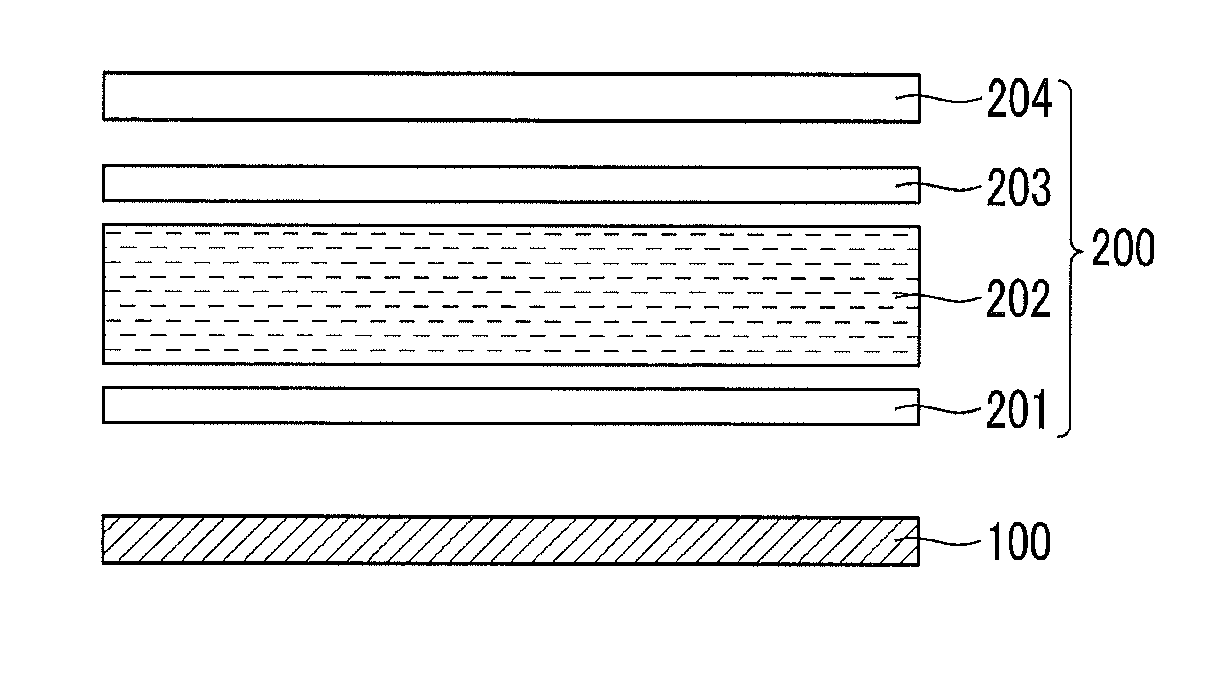
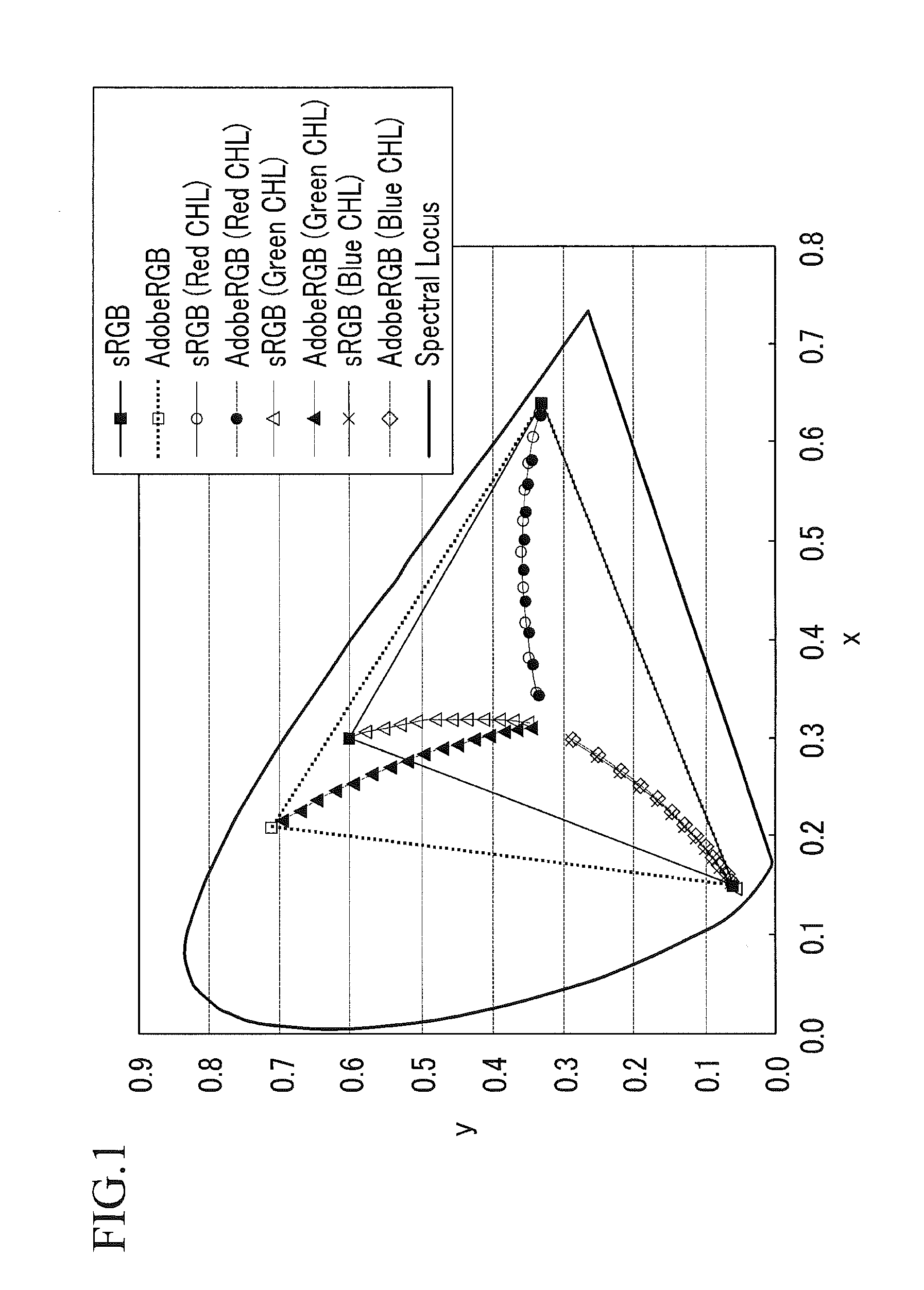
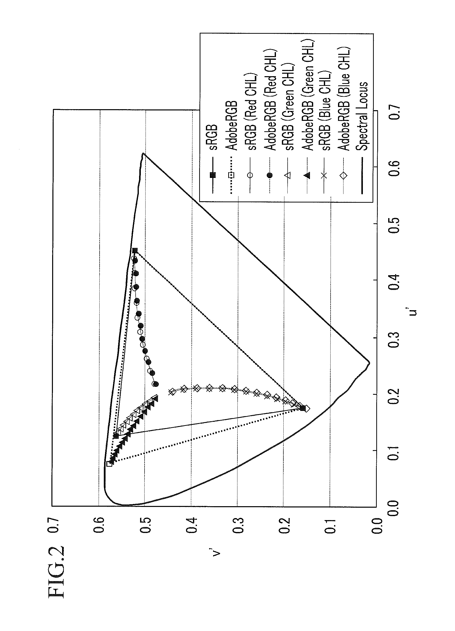
[0012]Provided is a white light emitting diode that effectively includes an Adobe RGB color space, and effectively provides gamut mapping of the color image information that is encoded and transferred by sRGB or Adobe RGB standards.

Problems solved by technology

Particularly, for use as a backlight of a liquid crystal display, a method of using a tri-color (red, green, and blue, or “RGB”) light emitting diode having excellent efficiency and color purity has been suggested, however it has a drawback of poor price competitiveness due to its high manufacturing cost and complicated operation circuit.
However, since the white LED light combining the blue light emitting diode with the YAG:Ce phosphor has only a part of the spectrum of the visible ray region, it has a low color rendering index, and when passing through a red, green, or blue color filter, many light components fail to pass through the color filter thus causing efficiency loss.
Thereby, it has low color purity and thus is not suitable for a display device requiring high definition such as a television (“TV”).
However, a suitable material that is capable of exciting an inorganic phosphor that is excited by relatively high energy to a blue wavelength of the visible light region has not yet been developed, and a thus-far developed green phosphor has low stability and color purity.
Further, a problem of low efficiency of a red phosphor has not yet been settled, and thus the method has a limitation in that color purity and light efficiency required in a light emitting diode for a backlight unit cannot be secured.

Method used


Image

  • White light emitting diode and liquid crystal display including the same
  • White light emitting diode and liquid crystal display including the same
  • White light emitting diode and liquid crystal display including the same

Examples


preparation example 1

Synthesis of Green Light Emitting Multi-Layered Semiconductor Nanocrystal

[0070]16 grams (g) of trioctylamine (“TOA”), 0.128 g of octadecylphosphonic acid, and 0.1 millimole (mmol) of cadmium oxide are simultaneously introduced into a 125 milliliter (mL) flask equipped with a reflux condenser, and the reaction temperature is controlled to about 300 degrees Celsius (° C.) while agitating the reaction mixture. Separately, Se powder is dissolved in trioctylphosphine (“TOP”) to prepare a Se-TOP complex solution with a Se concentration of about 2 moles (M). To the agitated reaction mixture, 2 mL of the 2 M Se-TOP complex solution is rapidly implanted, and the mixture is reacted for about 2 minutes. After the reaction is completed, the temperature of the reaction mixture is lowered to room temperature as soon as possible, a non-solvent ethanol is added thereto, and centrifugation is conducted. A supernatant of the solution excluding the centrifuged precipitate is discarded, and the precipi...

preparation example 2

Synthesis of Red Light Emitting Multi-Layered Semiconductor Nanocrystal

[0073]32 g of TOA, 1.8 g of oleic acid, and 1.6 mmol of cadmium oxide are simultaneously introduced into a 125 mL flask equipped with a reflux condenser, and the reaction temperature is controlled to about 300° C. while agitating the reaction mixture. 0.2 mL of the 2 M Se-TOP complex solution synthesized in Example 1 is rapidly implanted in the reactant, and after 1 minute 30 seconds, 0.8 mmol of octyl thiol mixed with 6 mL of TOA is slowly implanted therein. After reaction for about 40 minutes, 16 mL of a separately synthesized zinc oleate complex solution is slowly implanted.

[0074]The zinc oleate complex solution is synthesized by introducing 4 mmol of zinc acetate, 2.8 g of oleic acid, and 16 g of TOA into a 12 mL flask equipped with a reflux condenser, and controlling reaction temperature to about 200° C. while agitating the reaction mixture. After lowering the temperature to about 100° C. or less, the zinc o...

example 1

Manufacture of White Light Emitting Diode

[0076]To the green light emitting semiconductor nanocrystal synthesized in Preparation Example 1 and the red light emitting semiconductor nanocrystal synthesized in Preparation Example 2, a mixed solution of hexane and ethanol with a volume ratio of about 6:4 is added, and the mixture is centrifuged at about 6000 revolutions per minute (rpm) for about 10 minutes to obtain a precipitate. To the obtained precipitate, a chloroform solvent is added to prepare a solution of about 1 percent by weight (wt %) of the choloroform solvent. As an epoxy resin, SJ4500 A and SJ4500 B manufactured by Dow Corning® corporation are mixed at a volume ratio of about 1:1 beforehand, and air bubbles are removed. 1 wt % of the green light emitting semiconductor nanocrystal, 1 wt % of the red light emitting semiconductor nanocrystal, 0.1 mL of the chloroform solution, and 0.1 mL of the epoxy resin are mixed, and the mixture is agitated so as to be uniform and maintai...


PUM

PropertyMeasurementUnit
light emitting peak wavelengthaaaaaaaaaa

Abstract

A white light emitting diode includes a blue light emitting diode (“LED”) light source, and a light conversion layer which converts incident light from the blue LED light source into white light. The light conversion layer includes a green light emitting semiconductor nanocrystal and a red light emitting semiconductor nanocrystal. The white light emitting diode has a red, green and blue color (“RGB”) color locus which is within a chrominance error range (±4ΔE*ab) locus from the constant hue locus of each of sRGB color coordinates, or within a chrominance error range (±4ΔE*ab) locus from the constant hue locus of each of AdobeRGB color coordinates.

Description

CROSS-REFERENCE TO RELATED APPLICATIONS[0001]This application claims priority to Korean Patent Application No. 10-2010-0067095 filed on Jul. 12, 2010, and all the benefits accruing therefrom under 35 U.S.C. §119, the entire contents of which is incorporated herein by reference.BACKGROUND[0002]1. Field[0003]Provided is a white light emitting diode (“LED”) and a liquid crystal display device including the same.[0004]2. Description of the Related Art[0005]A white light emitting diode using a semiconductor is in the spotlight as one of next generation light emitting devices that are capable of replacing existing light emitting devices, due to its long life-span, capability of being down-sized, low power consumption, and environmentally friendly characteristic of being mercury free. The white light emitting diode is also used for an instrument panel of automobiles, a backlight of liquid crystal displays (“LCDs”), and the like.[0006]Particularly, for use as a backlight of a liquid crystal...

Claims


Application Information

Patent Timeline
Patent Type & Authority Applications(United States)
IPC IPC(8): G02F1/13357F21V9/00
CPCH01L33/502H01L33/504C09K11/02C09K11/565C09K11/883G02F1/133603H01L33/30Y02B20/181B82Y20/00H01L33/58Y10S977/95H01L33/28G02F1/133609G02F2001/133614H01L2224/16145H01L2224/14H01L2224/48091Y02B20/00G02F1/133614H01L2924/00014H01L33/50
Inventor IM, SEOUNG-JAECHOI, SEO-YOUNGJANG, EUN-JOO
Owner SAMSUNG ELECTRONICS CO LTD
Why Eureka
Try Eureka