Magnetic core plasmon antenna with improved coupling efficiency

a plasmon antenna and magnetic core technology, applied in the field of magnetic read/write head fabrication, can solve the problems of reducing so as to achieve significant affecting the coupling efficiency of plasmon mod

Active Publication Date: 2012-01-12
HEADWAY TECH INC
View PDF5 Cites 25 Cited by
  • Summary
  • Abstract
  • Description
  • Claims
  • Application Information

AI Technical Summary

Benefits of technology

[0031]It is a first object of the present invention to produce a TAMR head structure in which the separation between the application point of maximum magnetic field to a magnetic medium and the point being heated on that same magnetic medium is optimized, without significantly affecting the plasmon mode coupling efficiency to the optical mode in the antenna of the TAMR head structure.
[0032]It is a second object of this invention to minimize the energy loss during the coupling of the plasmon mode in the antenna to the optical mode in the waveguide of the TAMR head structure.
[0034]These objects will be achieved by means of a plasmon antenna design in a TAMR head in which the MCA has a core of magnetic material, such as CoFe or NiFe, overcoated with a plasmon generating layer (PGL) of non-magnetic highly conductive metal, such as Au or Ag, that is formed to a variable thickness and in which the plasmon mode will be generated. Within the coupling length of optical mode to plasmon mode coupling in the PGL, the thickness of the PGL will be made sufficient to impose little loss of coupling efficiency. The PGL thickness then is quickly reduced as the ABS of the TAMR head is approached so that the magnetic core edge of the antenna ((24) in FIG. 4) is much closer to the PGL edge ((27) in FIG. 4). Thus, as can be seen in the graphical representation of FIG. 5, the separation between magnetic field peak and heating peak is reduced. Since the thin portion of the PGL only occupies a short portion of the MCA close to the ABS, the total efficiency of the plasmon coupling will be very little affected.
[0042]For the MCA with variable thickness PGL of FIG. 8B, the length of the thin portion (36) is 100 nm and the thickness of this portion, (34) is varied between 20 nm and 200 nm. The length of the variable thickness transition region (30) is 200 nm. The thickness of the thick region (35) is 190 nm. The graph of C shows that the tapered PGL has about twice the plasmon coupling (or generation) efficiency of the uniform PGL at an ABS thickness of 20 nm. The trend lines of the graph show that the advantage of the tapered MCA over the uniform MCA is even larger at thinner ABS PGL thicknesses. Such an advantage makes the tapered MCA ideal for reducing the spacing between the magnetic field profile and the heating profile while keeping high enough heating in the medium as a result of the efficient coupling of the optical to plasmon modes.

Problems solved by technology

This latter effect is the thermal instability of the extremely small regions on which information must be recorded, in order to achieve the required data densities.
1. The need for a stronger writing field that is necessitated by the highly anisotropic and coercive magnetic media.
2. The need for a smaller write head of sufficient definition to produce the high areal write densities, which write heads, disadvantageously, produce a smaller field gradient and broader field profile.
Satisfying these requirements simultaneously may be a limiting factor in the further development of the present magnetic recording scheme used in state of the art hard-disk-drives (HDD).
If that is the case, further increases in recording area density may not be achievable within those schemes.
However, in the prior art a problem still exists in aligning the optical heating profile within the region of energy transfer at the medium surface, with the magnetic field profile generated by the write head.
Although this location will allow sufficient writing resolution with enough heating, it is not the optimal positioning of the two curves relative to each other.
Due to structural limitations, caused, for example, by the thickness and arrangement of the WG and by choice of the PA design, difficulties in alignments during fabrication, etc., optimal alignment of the heating and field profiles cannot be obtained.
The prior arts cited above do not address this trade-off or methods of dealing with it advantageously.

Method used


Image

  • Magnetic core plasmon antenna with improved coupling efficiency
  • Magnetic core plasmon antenna with improved coupling efficiency
  • Magnetic core plasmon antenna with improved coupling efficiency

Examples


first embodiment

[0065]Referring to schematic FIGS. 10 A, B and C, there is shown a side view (A), an ABS view (B) and a vertical cross-sectional view (C) of a first embodiment of a TAMR head that has a magnetic write pole (shaped so that it also forms a magnetic core for the plasmon antenna) (31) over which is formed a PGL of varying thickness (32). There is also an optical waveguide (33) adjacent to the plasmon antenna. Thus, the magnetic core of the plasmon antenna is an integral part of the MP and is, in fact, formed from the material of the MP itself. The PGL conformally covers two opposite sides of the core.

[0066]In this embodiment and all other embodiments the ABS cross-sectional shape of the MP has been given an exemplary trapezoidal form, with the magnetic core of the antenna either projecting out from the widest edge of the MP if it is formed as an integral part of the MP (as in this first embodiment), or adjacent to the widest edge of the MP, if it is a separate core. The antenna core has...

second embodiment

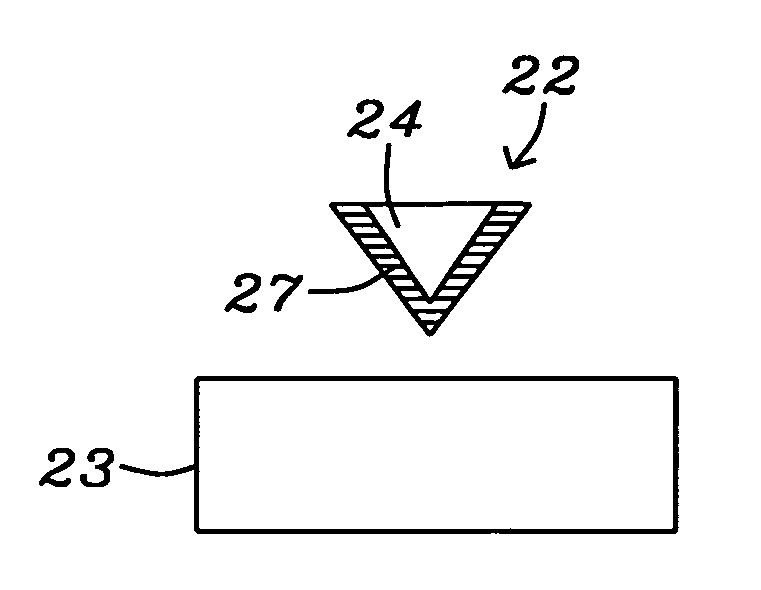
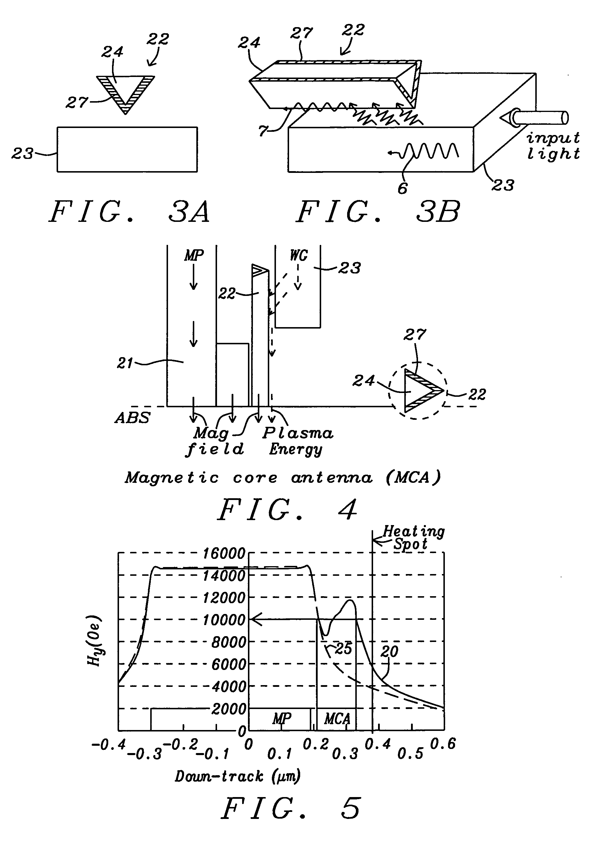
[0070]Referring now to schematic FIGS. 11 A, B and C, there is shown a second embodiment that is in every respect the same as the first embodiment except that the MP (39) and the MCA ((31 and (32)) are separate and disconnected structures. Note that the MP is here labeled (39) to distinguish it from the separate magnetic core (31) of the MCA, which in this embodiment has the shape of a triangular prism with its vertex being a straight line that is substantially parallel to the MP. In the following embodiments, when the MP also forms the core of the MCA it will be numbered (31), when the MP is separate from the core of the MCA (as in this embodiment), the MP will be numbered (39) and the core of the MCA will be numbered (31).

[0071]During recording, the magnetic field from the MP (39) also magnetizes the magnetic core (31) of the MCA, which produces a magnetic write field in the medium in addition to the field of the MP. Separation between the MP and the MCA is preferably less than 10...

third embodiment

[0072]Referring to schematic FIGS. 12 A, B and C, there is shown a schematic side view, an ABS view and a vertical cross-sectional view of a third embodiment of the present invention, in which there is formed a TAMR head that, like the first embodiment, includes an MCA that is a variable thickness PGL (32) formed directly on a portion of the MP (31) so that the MCA becomes an integral part of the MP. As in the first embodiment there is a WG (33) adjacent to the vertex of the PGL and alongside the thickest portion of the PGL for the most efficient coupling of optical and plasmon energies. During the recording process, the magnetic field is generated by the magnetic core (31) of the MCA and transmitted into the recording medium. The optical mode in the WG (33) couples to the PGL and generates a plasmon mode that is transmitted along the MCA towards the ABS of the TAMR head. The near field of this plasmon mode impinges on the recording medium and heats it locally. The PGL (32) is thinn...


PUM

PropertyMeasurementUnit
lengthaaaaaaaaaa
lengthaaaaaaaaaa
thicknessaaaaaaaaaa

Abstract

A TAMR (Thermal Assisted Magnetic Recording) write head uses the energy of optical-laser generated plasmons in a magnetic core plasmon antenna to locally heat a magnetic recording medium and reduce its coercivity and magnetic anisotropy. To enable the TAMR head to operate most effectively, the maximum gradient and value of the magnetic recording field should be at a point of the magnetic medium that is as close as possible to the point being heated. In addition, the coupling between the optical mode and the plasmon mode should be efficient so that maximum energy is transmitted to the medium. The present invention achieves both these objects by surrounding the magnetic core of a plasmon antenna by a variable thickness plasmon generating layer, whose thinnest and shortest portion is at the ABS end of the TAMR head and whose thickest and longest portion efficiently couples to the optical mode of a waveguide to produce a plasmon.

Description

BACKGROUND OF THE INVENTION[0001]1. Field of the Invention[0002]This invention relates to the fabrication of magnetic read / write heads that employ TAMR (thermally assisted magnetic recording) to enable writing on magnetic media having high coercivity and high magnetic anisotropy. More particularly, it relates to the use of a plasmon antenna (PA) to transfer the required thermal energy from the read / write head to the media.[0003]2. Description of the Related Art[0004]Magnetic recording at area data densities of between 1 and 10 Tera-bits per in2 involves the development of new magnetic recording media, new magnetic recording heads and, most importantly, a new magnetic recording scheme that can delay the onset of the so-called “superparamagnetic” effect. This latter effect is the thermal instability of the extremely small regions on which information must be recorded, in order to achieve the required data densities. A way of circumventing this thermal instability is to use magnetic re...

Claims


Application Information

Patent Timeline
Patent Type & Authority Applications(United States)
IPC IPC(8): G11B5/02G11B5/127
CPCB82Y20/00G02B6/1226G11B2005/0021G11B5/3163G11B5/6088G11B5/314
Inventor ZHOU, YUCHENMALETZKY, TOBIASJIN, XUHUIBAI, ZHIGANGTAKANO, KENICHISCHRECK, ERHARD
Owner HEADWAY TECH INC
Why Eureka
Try Eureka